Instrukcja obsługi Hikvision DS-2CD8283F-EIZ
Hikvision
Kamera monitorująca
DS-2CD8283F-EIZ
Przeczytaj poniżej 📖 instrukcję obsługi w języku polskim dla Hikvision DS-2CD8283F-EIZ (95 stron) w kategorii Kamera monitorująca. Ta instrukcja była pomocna dla 4 osób i została oceniona przez 2 użytkowników na średnio 4.5 gwiazdek
Strona 1/95

Network Camera
User Manual
V5.0
UD.6L0201D1001A01
Hikvision Digital Technology Co., Ltd.
hp://www.hikvision.com

User Manual of Network Camera
1
This manual is applied the following camera models: to
Type
Model
Box camera I
DS-2CD883F-E(W), DS-2CD855(F)-E, DS-2CD854F(WD)-E(W),
DS-2CD853F-E(W), DS-2CD864F(WD)-E(W),
DS-2CD863PF(NF)-E(W), DS-2CD893PFWD(NFWD)-E(W),
DS-2CD833F-E(W),
DS-2CD893PF(NF)-E(W)
Dome camera I
DS-2CD733F-E(I)(Z), DS-2CD793PF(NF)-E(I)(Z),
DS-2CD793PFWD(NFWD)-E(I)(Z), DS-2CD763PF(NF)-E(I)(Z),
DS-2CD764FWD-E(I)(Z), DS-2CD764F-E(I)(Z), DS-2CD753F-E(I)(Z),
DS-2CD754F-E(I)(Z), DS-2CD754FWD-E(I)(Z)(B),
DS-2CD783F-E(I)(Z), DS-2CD755F-E(I)(Z)
Dome camera II
DS-2CD7233F-E(I)Z(H)(S), DS-2CD7253F-E(I)Z(H)(S),
DS-CD7254F-E(I)Z(H)(S), DS-CD7254FWD- E(I)Z(H)(S),
DS-2CD7255F- E(I)Z(H)(S), DS-2CD7283F-E(I)Z(H)(S),
DS-2CD7293PFWD(NFWD)- E(I)Z(H)(S),
DS-2CD7263NF(PF)- E(I)Z(H)(S), DS-2CD 7264FWD- E(I)Z(H)(S),
DS-2CD7293PF(NF)- E(I)Z(H)(S)
Dome camera III
DS-2CD2312-I5, DS-2CD2332- I5
Dome camera IV
DS-2CD2112-(I), DS-2CD2132-(I)
Dome Camera V
DS-2CD7353F-E(I)(S), DS-2CD7393(PF)(NF)(WD)-E(I)(S)
Dome Camera VI
DS-2CD2712F-I(S); DS-2CD2732F-I(S)
Bullet Camera I
DS-2CD8253F- E(I)(Z)(S), DS-2CD8233F-E(I)(Z)(S),
DS-2CD8264FWD-E(I)(Z)(S), DS-2CD8264F-E(I)(Z)(S),
DS-2CD8254F- E(I)(Z)(S), DS-2CD8254FWD- E(I)(Z)(S),
DS-2CD8283F- E(I)(Z)(S), DS-2CD8255F- E(I)(Z)(S),
DS-2CD4212F-IS, DS-2CD4212F-IZS, DS-2CD4212F-I,
DS-2CD4212F, DS-2CD4224-IZS, DS-2CD4224F-I
Bullet Camera II
DS-2CD864-EI(3)(5), DS-2CD855-EI(3)(5)
Bullet Camera III
DS-2CD2012-I, DS-2CD2032-I
Bullet Camera IV
DS-2CD2212-I(3)(5), DS-2CD2232-I(3)(5),
Bullet Camera V
DS-2CD2612F-I(S), DS-2CD2632F-I(S)
Cube Camera I
DS-2CD8133F-E(I)(W), DS-2CD8153F-E(I)(W)
Cube Camera II
DS-2CD8464F-E(I)(W), DS-2CD8433F-E(I)(W)
Mini Dome
Camera
DS-2CD7164-E,DS-2CD7153-E, DS-2CD7133-E

User Manual of Network Camera
© Hikvision Digital Technology Co., Ltd. All Rights Reserved.
2
Thank you for purchasing our product. If there are any quesons, or requests, please
do not hesitate to contact the dealer.
This manual applies to Network Camera.
This manual may contain several technical incorrect places or prinng errors, and the
content is subject to change without noce. The updates will be added to the new
version of this manual. We will readily improve or update the products or procedures
described in the manual.
DISCLAIMER STATEMENT
“Underwriters Laboratories Inc. (“UL”) has not tested the performance or reliability
of the security or signaling aspects of this product. UL has only tested for re, shock
or casualty hazards as outlined in UL’s Standard(s) for Safety, UL60950-1. UL
Cercaon does not cover the performance or reliability of the security or signaling
aspects of this product. UL MAKES NO REPRESENTATIONS, WARRANTIES OR
CERTIFICATIONS WHATSOEVER REGARDING THE PERFORMANCE OR RELIABILITY OF
ANY SECURITY OR SIGNALING RELATED FUNCTIONS OF THIS PRODUCT.”

User Manual of Network Camera
© Hikvision Digital Technology Co., Ltd. All Rights Reserved.
3
Regulatory Informaon
FCC Informaon
FCC compliance: This equipment has been tested and found to comply with the limits
for a digital device, pursuant to part 15 of the FCC Rules. These limits are designed to
provide reasonable protecon against harmful interference when the equipment is
operated in a commercial environment. This equipment generates, uses, and can
radiate radio frequency energy and, if not installed and used in accordance with the
instrucon manual, may cause harmful interference to radio communicaons.
Operaon of this equipment in a residenal area is likely to cause harmful
interference in which case the user will be required to correct the interference at his
own expense.
FCC Condions
This device complies with part 15 of the FCC Rules. Operaon is subject to the
following two condions:
1. This device may not cause harmful interference.
2. This device must accept any interference received, including interference that may
cause undesired operaon.
EU Conformity Statement
This product and - if applicable - the supplied accessories too are
marked with "CE" and comply therefore with the applicable
harmonized European standards listed under the Low Voltage Direcve
2006/95/EC, the EMC Direcve 2004/108/EC.
2002/96/EC (WEEE direcve): Products marked with this symbol cannot
be disposed of as unsorted municipal waste in the European Union.
For proper recycling, return this product to your local supplier upon
the purchase of equivalent new equipment, or dispose of it at
designated collecon points. For more informaon see: www.recyclethis.info.
2006/66/EC (battery direcve): This product contains a battery that
cannot be disposed of as unsorted municipal waste in the European
Union. See the product documentaon for specic battery informaon.
The baery is marked with this symbol, which may include leering to
indicate cadmium (Cd), lead (Pb), or mercury (Hg). For proper recycling, return the
baery to your supplier or to a designated collecon point. For more informaon see:
www.recyclethis.info.

User Manual of Network Camera
© Hikvision Digital Technology Co., Ltd. All Rights Reserved.
4
Safety Warnings and Cauons
Please pay attenon to the following warnings and cauons:
Hazardous Voltage may be present: Special measures and
precauons must be taken when using this device. Some potenals
(voltages) on the device may present a hazard to the user. This
device should only be used by employees from our company with
knowledge and training in working with these types of devices that
contain live circuits.
Power Supply Hazardous Voltage: AC mains voltages are present within the power
supply assembly. This device must be connected to a UL approved, completely
enclosed power supply, of the proper rated voltage and current. No user serviceable
parts inside the power supply.
System Grounding (Earthing): To avoid shock, ensure that all AC wiring is not
exposed and that the earth grounding is maintained. Ensure that any equipment to
which this device will be attached is also connected to properly wired grounded
receptacles and are approved medical devices.
Power Connect and Disconnect: The AC power supply cord is the
main disconnect device to mains (AC power).The socket outlet shall
be installed near the equipment and shall be readily accessible.
Installaon and Maintenance: Do not connect/disconnect any
cables to or perform installaon/maintenance on this device during an electrical
storm.

User Manual of Network Camera
© Hikvision Digital Technology Co., Ltd. All Rights Reserved.
5
Power Cord Requirements: The connector that plugs into the wall outlet must be a
grounding-type male plug designed for use in your region. It must have cercation
marks showing cercaon by an agency in your region. The connector that plugs
into the AC receptacle on the power supply must be an IEC 320, sheet C13, female
connector. See the following website for more informaon
hp://kropla.com/electric2.htm.
Lithium Battery: This device contains a Lithium Battery. There is a
risk of explosion if the battery is replaced by an incorrect type.
Dispose of used batteries according to the vendor’s instrucons
and in accordance with local environmental regulaons.
Perchlorate Material: Special handling may apply. See
www.dtsc.ca.gov/hazardouswaste/perchlorate. This noce is required by California
Code of Regulaons, Title 22, Division 4.5, Chapter 33: Best Management Pracces
for Perchlorate Materials. This device includes a baery which contains perchlorate
material.
Taiwan battery recycling:
Please recycle batteries.
Thermal and Mechanical Injury: Some components such as heat
sinks, power regulators, and processors may be hot; care should
be taken to avoid contact with these components.
Electro Magnec Interference: This equipment has not been
tested for compliance with emissions limits of FCC and similar internaonal
regulaons. This device is not, and may not be, offered for sale or lease, or sold, or
leased unl authorizaon from the United States FCC or its equivalent in other
countries has been obtained. Use of this equipment in a residenal locaon is
prohibited. This equipment generates, uses and can radiate radio frequency energy
which may result in harmful interference to radio communicaons. If this equipment
does cause harmful interference to radio or television recepon, which can be

User Manual of Network Camera
© Hikvision Digital Technology Co., Ltd. All Rights Reserved.
6
determined by turning the equipment on and off, the user is required to take
measures to eliminate the interference or discontinue the use of this equipment.
Lead Content:
Please recycle this device in a responsible manner. Refer to
local environmental regulations for proper recycling; do not
dispose of device in unsorted municipal waste.
User Manual of Network Camera
© Hikvision Digital Technology Co., Ltd. All Rights Reserved.
7
Safety Instrucon
These instrucons are intended to ensure that the user can use the product correctly
to avoid danger or property loss.
The precauon measure is divided into ‘Warnings’ and ‘Cauons’:
Warnings: Serious injury or death may be caused if any of these warnings are
neglected.
Cauons: Injury or equipment damage may be caused if any of these cauons are
neglected.
Warnings Follow these safeguards to
prevent serious injury or death.
Cauons Follow these precauons to
prevent potenal injury or material
damage.
Warnings:
Please adopt the power adapter which can meet the safety extra low voltage
(SELV) standard And source with DC 12V or AC 24V (depending on models. )
according to the IEC60950-1 and Limited Power Source standard.
If the product does not work properly, please contact your dealer or the nearest
service center. Never aempt to disassemble the camera yourself. (We shall not
assume any responsibility for problems caused by unauthorized repair or
maintenance.)
To reduce the risk of re or electrical shock, do not expose this product to rain or
moisture.
This installaon should be made by a qualied service person and should
conform to all the local codes.
Please install blackouts equipment into the power supply circuit for convenient
supply interrupon.
Please make sure that the ceiling can support more than 50(N) Newton gravies
if the camera is xed to the ceiling.
If the product does not work properly, please contact your dealer or the nearest
service center. Never aempt to disassemble the camera yourself. (We shall not
assume any responsibility for problems caused by unauthorized repair or
maintenance.)

User Manual of Network Camera
© Hikvision Digital Technology Co., Ltd. All Rights Reserved.
8
Cauons:
Make sure the power supply voltage is correct before using the camera.
Do not drop the camera or subject it to physical shock.
Do not touch sensor modules with ngers. If cleaning is necessary, use a clean
cloth with a bit of ethanol and wipe it gently. If the camera will not be used for
an extended period of me, put on the lens cap to protect the sensor from dirt.
Do not aim the camera lens at the strong light such as sun or incandescent lamp.
The strong light can cause fatal damage to the camera.
The sensor may be burned out by a laser beam, so when any laser equipment is
being used, make sure that the surface of the sensor not be exposed to the laser
beam.
Do not place the camera in extremely hot, cold temperatures (the operating
temperature should be between - °C ~ ), dusty or damp environment, and 10 60°C
do not expose it to high electromagnec radiaon.
To avoid heat accumulation, good venlaon is required for a proper operang
environment.
Keep out of water and any liquid.
While shipping, the camera should be packed in its original packing.
Improper use or replacement of the baery may result in hazard of explosion.
Please use the manufacturer recommended battery type.

User Manual of Network Camera
© Hikvision Digital Technology Co., Ltd. All Rights Reserved.
9
Contents
CHAPTER 1 SYSTEM REQUIREMENT ............................................................................................ 12
CHAPTER 2 NETWORK CONNECTION .......................................................................................... 13
2.1 S N C ETTING THE ETWORK AMERA OVER THE LAN .............................................................................. 13
2.1.1 Wiring over the LAN .......................................................................................................... 13
2.1.2 Detecng and Changing the IP Address ............................................................................. 14
2.2 S N C ETTING THE ETWORK AMERA OVER THE WAN ............................................................................15
2.2.1 Stac IP Connecon ........................................................................................................... 15
2.2.2 Dynamic IP Connecon ...................................................................................................... 16
CHAPTER 3 ACCESS TO THE NETWORK CAMERA ......................................................................... 18
3.1 A CCESSING BY EB ROWSERSW B ..................................................................................................... 18
3.2 A CCESSING BY LIENT OFTWAREC S ................................................................................................... 20
3.2.1 Accessing by iVMS-4200 Soware ..................................................................................... 20
3.2.2 Accessing by iVMS-4500 Soware ..................................................................................... 21
CHAPTER 4 -FI SETTINGS WI ........................................................................................................21
4.1 C ONFIGURING I ONNECTION IN ANAGE AND DW -FI C M A -HOC ODESM .................................................. 22
4.2 E W -F C ASY I I ONNECTION WITH FUNCTIONWPS ..............................................................................26
4.3 P IP ROPERTY ETTINGS FOR IRELESS ETWORK ONNECTIONS W N C ........................................................... 28
CHAPTER 5 LIVE VIEW ................................................................................................................ 29
5.1 L V P IVE IEW AGE .........................................................................................................................29
5.2 S TARTING IVE IEWL V ...................................................................................................................30
5.3 R ECORDING AND APTURING ICTURES ANUALLYC P M ........................................................................... 30
5.4 O PERATING PTZ CONTROL ...........................................................................................................31
5.4.1 PTZ Control Panel ............................................................................................................... 31
5.4.2 Seng / Calling a Preset .................................................................................................... 32
5.5 C ONFIGURING IVE IEW L V PARAMETERS ........................................................................................... 33
CHAPTER 6 NETWORK CAMERA CONFIGURATION ...................................................................... 33
6.1 C ONFIGURING LOCAL PARAMETERS ................................................................................................33
6.2 C ONFIGURING IME ETTINGST S ....................................................................................................... 35
6.3 C ONFIGURING ETWORK ETTINGSN S ................................................................................................ 37
6.3.1 Conguring TCP/IP Sengs ...............................................................................................37
6.3.2 Conguring Port Sengs ................................................................................................... 38
6.3.3 Conguring PPPoE Sengs ................................................................................................ 38
6.3.4 Conguring DDNS Sengs . ................................................................................................ 39
6.3.5 Conguring SNMP Sengs ................................................................................................ 41
6.3.6 Conguring 802.1X Sengs ............................................................................................... 42
6.3.7 Conguring QoS Sengs ................................................................................................... 43
6.3.8 Conguring FTP Sengs .................................................................................................... 44
6.3.9 Conguring UPnP™ Sengs ..............................................................................................45

User Manual of Network Camera
© Hikvision Digital Technology Co., Ltd. All Rights Reserved.
10
6.4 C ONFIGURING IDEO AND V A S UDIO ETTINGS..................................................................................... 46
6.4.1 Conguring Video Sengs ................................................................................................ 46
6.4.2 Conguring Audio Sengs ................................................................................................ 47
6.4.3 Conguring ROI Encoding .................................................................................................. 48
6.5 C ONFIGURING MAGE I PARAMETERS ................................................................................................ 48
6.5.1 Conguring Display Sengs .............................................................................................. 48
6.5.2 Conguring OSD Sengs ................................................................................................... 50
6.5.3 Conguring Text Overlay Sengs ...................................................................................... 52
6.5.4 Conguring Privacy Mask ..................................................................................................52
6.5.5 Conguring Picture Overlay ............................................................................................... 53
6.6 C ONFIGURING AND ANDLING LARMSH A .......................................................................................... 54
6.6.1 Conguring Moon Detecon ........................................................................................... 54
6.6.2 Conguring Tamper-proof Alarm ....................................................................................... 57
6.6.3 Conguring External Alarm Input ...................................................................................... 59
6.6.4 Conguring Alarm Output . ................................................................................................ 60
6.6.5 Handling Excepon ............................................................................................................ 61
6.6.6 Email Sending Triggered by Alarm ..................................................................................... 62
6.6.7 Conguring Snapshot Sengs ........................................................................................... 63
6.6.8 Face Detecon ................................................................................................................... 64
6.6.9 Conguring Other Alarms .................................................................................................. 65
6.6.10 Arming or Disarming the Camera .................................................................................. 70
CHAPTER 7 STORAGE SETTINGS .................................................................................................. 72
7.1 C ONFIGURING ETTINGSNAS S ....................................................................................................... 72
7.2 C ONFIGURING ECORDING CHEDULER S ............................................................................................. 73
CHAPTER 8 PLAYBACK ................................................................................................................ 78
CHAPTER 9 LOG SEARCHING ....................................................................................................... 80
CHAPTER 10 OTHERS .................................................................................................................... 81
10.1 M U A ANAGING SER CCOUNTS ........................................................................................................ 81
10.2 C ONFIGURING RTSP AUTHENTICATION ........................................................................................... 83
10.3 A V NONYMOUS ISIT ..................................................................................................................... 83
10.4 A F IP DDRESS ILTER ...................................................................................................................... 84
10.5 V D I IEWING EVICE NFORMATION ....................................................................................................86
10.6 M AINTENANCE........................................................................................................................... 87
10.6.1 Reboong the Camera ................................................................................................... 87
10.6.2 Restoring Default Sengs .............................................................................................87
10.6.3 Imporng/Exporng Conguraon File ........................................................................ 87
10.6.4 Upgrading the System .................................................................................................... 88
10.7 - S RS 232 ETTINGS ......................................................................................................................88
10.8 - S RS 485 ETTINGS ......................................................................................................................89
APPENDIX ........................................................................................................................................90
A 1 SADP SPPENDIX OFTWARE NTRODUCTIONI ............................................................................................. 90

User Manual of Network Camera
© Hikvision Digital Technology Co., Ltd. All Rights Reserved.
11
A 2 PPPENDIX ORT APPINGM ..................................................................................................................... 92

User Manual of Network Camera
© Hikvision Digital Technology Co., Ltd. All Rights Reserved.
12
Chapter 1 System Requirement
Operang System: Microso Windows XP SP1 and above version / Vista / Win7 /
Server 2003 / Server 2008 32bits
CPU: Intel Penum IV 3.0 GHz or higher
RAM: 1G or higher
Display: 1024×768 resoluon or higher
Web Browser: Internet Explorer 6.0 and above version, Apple Safari 5.02 and above
version, Mozilla Firefox 3.5 and above version and Google Chrome8 and above
versions.

User Manual of Network Camera
13
Chapter 2 Network Connecon
Before you start:
If you want to set the network camera via LAN (Local Area Network), please a
refer to Secon 2.1 Seng the Network Camera over the LAN.
If you want to set the network camera via WAN (Wide Area Network), please a
refer to Secon 2.2 Seng the Network Camera over the WAN.
2.1 Setng the Network Camera over the LAN
Purpose:
To view and congure the camera via LAN, you need to connect the network a
camera in the same subnet with your computer, and install the SADP or iVMS-4200
soware to search and change the IP of the network camera.
Note: For the detailed introducon of SADP, please refer to Appendix 1.
2.1.1 Wiring over the LAN
The following gures show the two ways of cable connecon of network camera a
and computer: a
Purpose:
To test the network camera, you can directly connect the network camera to the
computer with a network cable as shown in Figure 2-1.
Refer to the Figure 2-2 set the network camera over the LAN via a switch or a to
router.
Figure 2-1 Connecng Directly
Figure 2-2 Connecng via a Switch or Router a

User Manual of Network Camera
© Hikvision Digital Technology Co., Ltd. All Rights Reserved.
14
2.1.2 Detecng and Changing the IP Address
You need the IP address to visit the network camera.
Steps:
1. To get the IP address, you can choose either of the following methods:
Use SADP, a soware tool which can automacally detect online the
network cameras in the LAN and list the device informaon including IP
address, subnet mask, port number, device serial number, device version,
etc., shown in Figure 2-3.
Use the client soware to list the online devices. Please refer to the user
manual of client soware for detailed informaon.
2. Change the IP address and subnet mask to the same subnet as that of your
computer.
3. Enter the IP address of network camera in the address eld of the web browser
to view the live video.
Notes:
The default IP address is 192.0.0.64 and the port number is 8000. The default
user name is admin, and password is 12345.
For accessing the network camera from different subnets, please set the gateway
for the network camera aer you logged in. For detailed informaon, please
refer to Secon 5.3.1 Conguring TCP/IP Sengs.
Figure 2-3 SADP Interface

User Manual of Network Camera
© Hikvision Digital Technology Co., Ltd. All Rights Reserved.
15
2.2 Setng the Network Camera over the WAN
Purpose:
This secon explains how to connect the network camera to the WAN with a stac IP
or a dynamic IP.
2.2.1 Stac IP Connecon
Before you start:
Please apply a stac IP from an ISP (Internet Service Provider). With the static IP
address, you can connect the network camera via a router or connect it to the WAN
directly.
Connecng the network camera via a router
Steps:
1. Connect the network camera to the router.
2. Assign a LAN IP address, the subnet mask and the gateway. Refer to Secon 2.1.2
Detecng and Changing the IP Address for detailed IP address conguraon of
the camera.
3. Save the stac IP in the router.
4. Set port mapping, E.g 80, 8000, 8200 and 554 ports. The steps for port mapping .,
vary depending on dierent routers. Please call the router manufacturer for
assistance with port mapping.
Note: Refer to Appendix 2 for detailed informaon abou port mapping. t
5. Visit the network camera through a web browser or the client soware over the
internet.
Figure 2-4 Accessing the Camera through Router with Stac IP
Connecng the network camera with stac IP directly
You can also save the static IP in the camera and directly connect it to the internet
without using a router. Refer to Secon 2.1.2 Detecng and Changing the IP Address
for detailed IP address conguraon of the camera.
Figure 2-5 Accessing the Camera with Stac IP Directly

User Manual of Network Camera
© Hikvision Digital Technology Co., Ltd. All Rights Reserved.
16
2.2.2 Dynamic IP Connecon
Before you start:
Please apply a dynamic IP from an ISP. With the dynamic IP address, you can connect
the network camera a modem or a router. to
Connecng the network camera via a router
Steps:
1. Connect the network camera to the router.
2. In the camera, assign a LAN IP address, the subnet mask and the gateway. Refer
to Secon 2.1.2 Detecng and Changing the IP Address for detailed LAN
conguraon.
3. In the router, set the PPPoE user name, password and confirm the password.
4. Set port mapping. E.g. 80, 8000, 8200 and 554 ports. The steps for port mapping
vary depending on dierent routers. Please call the router manufacturer for
assistance with port mapping.
Note: Refer to Appendix 2 for detailed informaon about port mapping.
5. Apply a domain name from a domain name provider.
6. Congure the DDNS sengs in the seng interface of the router.
7. Visit the camera via the applied domain name.
Connecng the network camera via a modem
Purpose:
This camera supports the PPPoE auto dial-up funcon. The camera gets a public IP
address by ADSL dial-up aer the camera is connected to a modem. You need to
congure the PPPoE parameters of the network camera. Refer to Secon 5.3.3
Conguring PPPoE Setngs for detailed conguraon.
Figure 2-6 Accessing Camera with Dynamic IP the
Note: The obtained IP address is dynamically assigned via PPPoE, so the IP address
always changes aer reboong the camera. To solve the inconvenience of the
dynamic IP, you need to get a domain name from the DDNS provider (E.g.
DynDns.com). Please follow below steps for normal domain name resoluon and
private domain name resoluon to solve the problem.
Normal Domain Name Resoluon

User Manual of Network Camera
© Hikvision Digital Technology Co., Ltd. All Rights Reserved.
17
Figure 2-7 Normal Domain Name Resoluon
Steps:
1. Apply a domain name from a domain name provider.
2. Congure the DDNS sengs in the DDNS Setngs interface of the network
camera. Refer to Secon 5.3.4 Conguring DDNS Setngs for detailed
conguraon.
3. Visit the camera via the applied domain name.
Private Domain Name Resoluon
Figure 2-8 Private Domain Name Resoluon
Steps:
1. Install and run the IP Server soware in a computer with a static IP.
2. Access the network camera through the LAN with web browser or client a the
soware.
3. Enable DDNS and select Server as the protocol type. Refer to IP Secon 5.3.4
Conguring DDNS Sengs for detailed conguraon.
User Manual of Network Camera
18
Chapter 3 Access to the Network
Camera
3.1 Accessing by Web Browsers
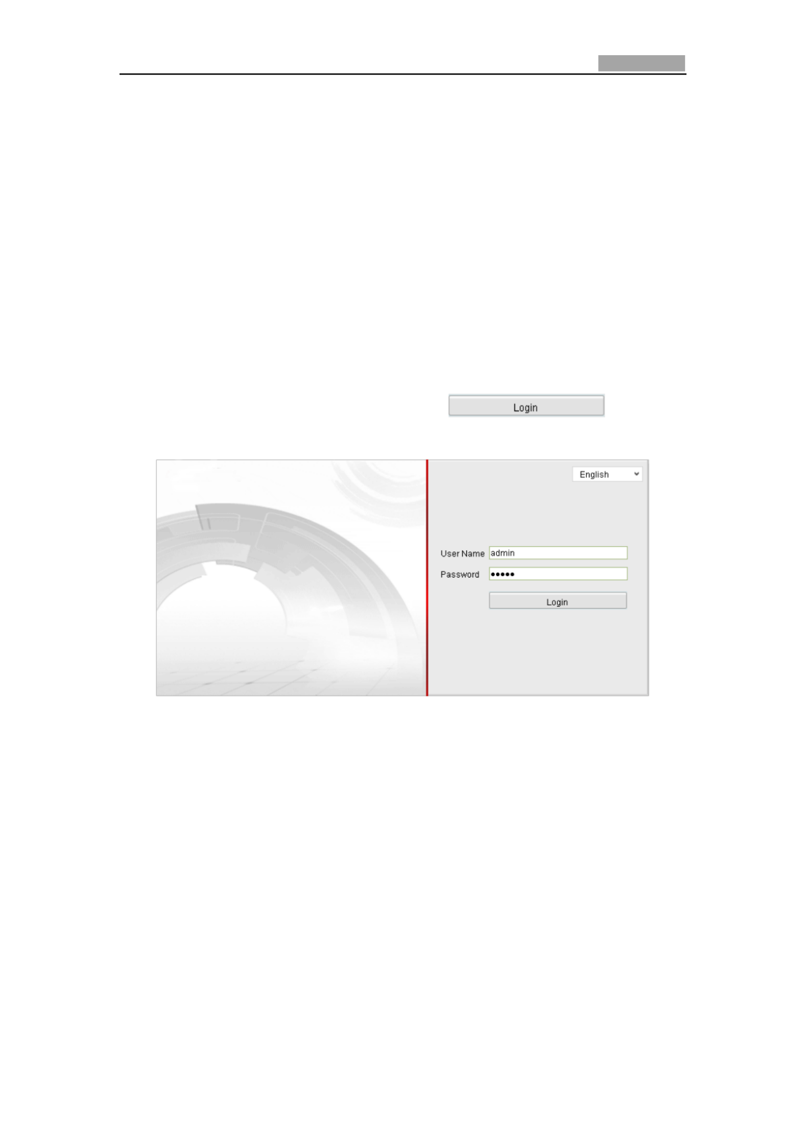
Steps:
1. Open the web browser.
2. In the address eld, input the IP address of the network camera, e.g., 192.0.0.64
and press the key to enter the login interface. Enter
3. Input the user name and passwo and click . rd
Note: The default user name is admin, password is 12345.
Figure 3-1 Login Interface
4. Install the plug-in before viewing the live video and operang the camera.
Please follow the installaon prompts to install the plug-in.

User Manual of Network Camera
© Hikvision Digital Technology Co., Ltd. All Rights Reserved.
19
Figure 3-2 Download and Install Plug-in
Figure 3-3 Install Plug-in (1)
Figure 3-4 Install Plug-in (2)
User Manual of Network Camera
© Hikvision Digital Technology Co., Ltd. All Rights Reserved.
20
Figure 3-5 Install Plug-in (3)
Note: You may have to close the web browser to install the plug-in. Please reopen
the web browser and log in again aer installing the plug-in.
3.2 Accessing by Client Soware
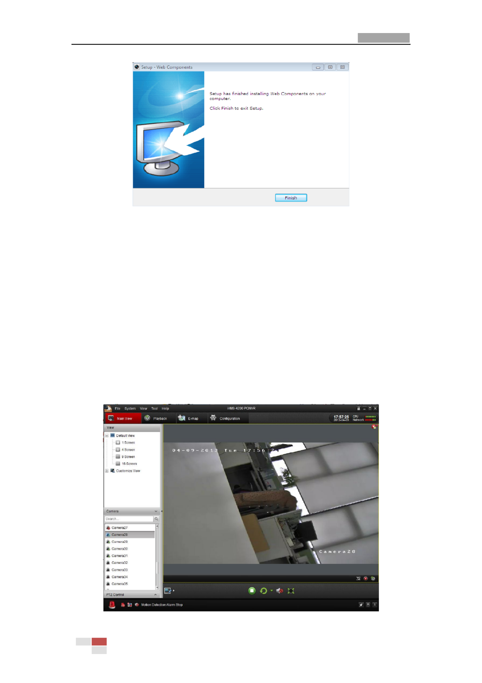
3.2.1 Accessing by iVMS-4200 Soware
The product CD contains the iVMS-4200 client soware (Client or PCNVR) You can .
view the live video and manage the camera with the client soware .
Follow the installaon prompts to install the soware The control panel and live .
view interface of iVMS-4200 are shown as bellow.

User Manual of Network Camera
© Hikvision Digital Technology Co., Ltd. All Rights Reserved.
21
Figure 3-6 iVMS-4200 Live View
Figure 3-7 iVMS-4200 Conguraon Panel
Note: For detailed informaon about iVMS-4200 client soware, please refer to the
user manual of the iVMS-4200 soware.
3.2.2 Accessing by iVMS-4500 Software
To view the camera with a mobile phone, install the iVMS-4500 client soware in
your mobile phone. You can find the soware in the CD in the package, and you can
also download the software from our website www.hikvision.com.
Note: For detailed informaon about iVMS-4500 client soware, please refer to the
user manual of iVMS-4500 software.
Chapter 4 Wi-Fi Sengs
Purpose:
By connecng to the wireless network, you don t need to use cable of any kind for ’
network connecon, which is very convenient for the actual surveillance applicaon.
Note:
This chapter is only applicable for the cameras with the Wi-Fi module built-in.

User Manual of Network Camera
© Hikvision Digital Technology Co., Ltd. All Rights Reserved.
22
4.1 Conguring Wi-Fi Connecon in Manage and
Ad-hoc Modes
Before you start:
A wireless network must be congured .
Wireless Connecon in Manage Mode
Steps:
1. Enter the Wi-Fi conguraon interface.
Conguraon> Advanced Conguraon> Network> Wi-Fi
Figure 4-1 Wireless Network List
2. Click buon to search the online wireless connecons.
3. Click to choose a wireless connecon on the list.
Figure 4-2 Wi-Fi Seng- Manage Mode
4. Check the checkbox to select the and the Network mode as Manage, Security
mode Encrypon Type and the of the network is automacally shown when
you select the wireless network, please don t change it manually. ’
Note: These parameters are exactly idencal with those of the router.
5. Enter the key to connect the wireless network. The key should be that of the
wireless network connecon you set on the router.
Wireless Connecon in -hoc Mode Ad

User Manual of Network Camera
© Hikvision Digital Technology Co., Ltd. All Rights Reserved.
23
If you choose the -hoc mode, you don t need to connect the wireless camera Ad ’
via a router. The scenario is the same as you connect the camera and the PC directly
with a network cable.
Steps:
1. Choose Ad-hoc mode.
Figure 4-3 Wi-Fi Seng- -hoc Ad
2. Customize a SSID for the camera.
3. Choose the Security Mode of the wireless connecon.
Figure 4-4
Figure 4-5 Security Mode- -hoc Mode Ad
4. Enable the wireless connecon funcon for your PC.
5. On the PC side, search the network and you can see the SSID of the
camera listed.
Figure 4-6 Ad-hoc Connecon Point
6. Choose the SSID and connect.
Security Mode Descripon:

User Manual of Network Camera
© Hikvision Digital Technology Co., Ltd. All Rights Reserved.
24
You can choose the Security Mode as not encrypted, WEP, WPA-personal, –
WPA-enterprise, WPA2-personal, WPA2-enterprise.
WEP mode:
Authencaon - Select Open or Shared Key System Authencaon, depending on
the method used by your access point. Not all access points have this opon, in
which case they probably use Open Sys-tem, which is somemes known as SSID
Authencation.
Key length - This sets the length of the key used for the wireless encrypon, 64 or
128 bit. The encrypon key length can somemes be shown as 40/64 and
104/128.
Key type - The key types available depend on the access point being used. The
following opons are available:
HEX - Allows you to manually enter the hex key.
ASCII - In this method the string must be exactly 5 characters for 64-bit WEP
and 13 characters for 128-bit WEP.
WPA-personal and WPA2-personal Mode:
Enter the required Pre-shared Key for the access point, which can be a hexadecimal
number or a passphrase.

User Manual of Network Camera
© Hikvision Digital Technology Co., Ltd. All Rights Reserved.
25
WPA- enterprise and WPA2-enterprise Mode:
Choose the type of client/server authenticaon being used by the access point;
EAP-TLS or EAP-PEAP.
EAP-TLS
Identy - Enter the user ID to present to the network.
Private key password Enter the password for your user ID. –
EAPOL version - Select the version used (1 or 2) in your access point.
CA Cercates - Upload a CA cercate to present to the access point for
authencation.
EAP-PEAP:
User Name - Enter the user name to present to the network
Password - Enter the password of the network
PEAP Version - Select the PEAP version used at the access point.
Label - Select the label used by the access point.
EAPOL version - Select version (1 or 2) depending on the version used at the
access point
CA Certicates - Upload a CA certicate to present to the access point for
authencation

User Manual of Network Camera
© Hikvision Digital Technology Co., Ltd. All Rights Reserved.
26
4.2 Easy Wi-Fi Connection with WPS function
Purpose :
The seng of the wireless network connecon is never easy. To avoid the
complex seng of the wireless connecon you can enable the WPS funcon.
WPS (Wi-Fi Protected Setup refers to the easy conguraon of the encrypted )
connecon between the device and the wireless router. The WPS makes it easy to
add new devices to an existing network without entering long passphrases. There are
two modes of the WPS connecon, the PBC mode and the PIN mode.
Note: If you enable the WPS funcon, you don t need to congure the parameters ’
such as the encrypon type and you don t need to know the key of the wireless ’
connecon.
Steps:
Figure 4-7 Wi-Fi Setngs - WPS
PBC Mode:
PBC refers to the Push-Buon-Conguraon, in which the user simply has to
push a buon, either an actual or virtual one (as the buon on the
conguraon interface of the IE browser), on both the Access Point (and a registrar
of the network) and the new wireless client device.
1. Check the checkbox of to enable WPS.
2. Choose the connecon mode as PBC.
Note: Support of this mode is mandatory for both the Access Points and the
connecng devices.
3. Check on the Wi-Fi router to see if there is a WPS buon. If yes push the
buon and you can see the indicator near the buon start ashing, which
means the WPS funcon of the router is enabled. For detailed operaon,
please see the user guide of the router.
4. Push the WPS buon to enable the funcon on the camera.

User Manual of Network Camera
© Hikvision Digital Technology Co., Ltd. All Rights Reserved.
27
If there is not a WPS button on the camera, you can also click the virtual button to
enable the PBC function on the web interface .
Click button.
When the PBC mode is both enabled in the router and the camera, the camera and
the wireless network is connected automatically.
PIN Mode:
The PIN mode requires a Personal Identification Number (PIN) to be read from either
a sticker or the display on the new wireless device. This PIN must then be entered to
connect the network, usually the Access Point of the network.
Steps:
1. Choose a wireless connection on the list and the SSID is shown.
Figure 4-8 Wi-Fi Settings WPS PIN Mode –
2. Choose the .
If the PIN code is generated from the router side, you should enter the PIN code you
get from the router side in the field.
3. Click button.
Or
User Manual of Network Camera
© Hikvision Digital Technology Co., Ltd. All Rights Reserved.
28
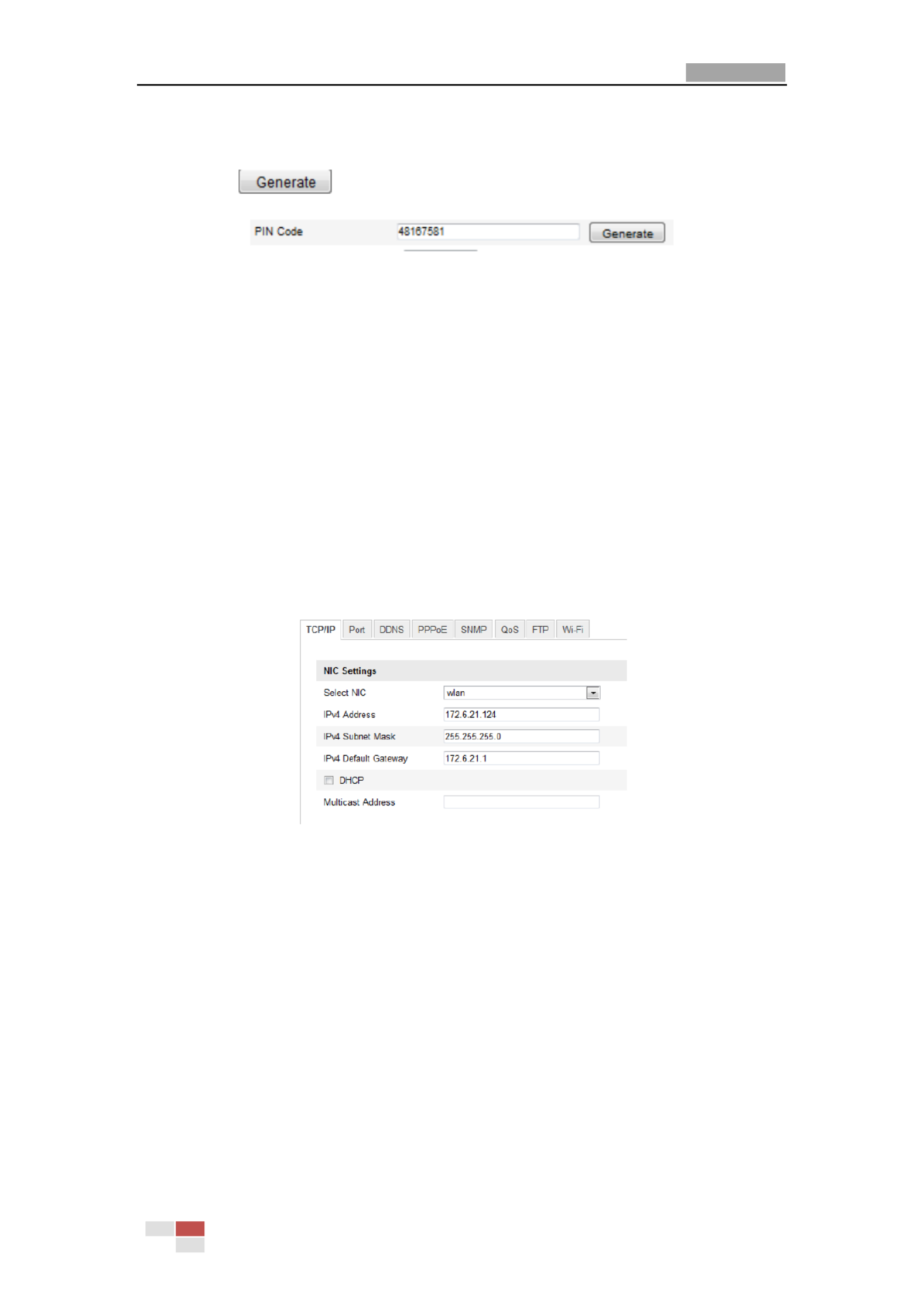
You can generate the PIN code on the camera side. And the expired time for the PIN
code is 120 seconds.
1. Click
2. Enter the code to the router, in the example, enter 48167581 to the router.
4.3 IP Property Settings for Wireless Network
Connection
The default IP address of wireless network interface controller is 192.168.1.64. When
you connect the wireless network you can change the default IP.
Steps:
1. Enter the TCP/IP configuration interface.
Configuration> Advanced Configuration> Network> TCP/IP
or
Configuration> Basic Configuration> Network> TCP/IP
Figure 4-9 TCP/IP Settings
2. Select the NIC as wlan.
3. Customize the IPv4 address, the IPv4 Subnet Mask and the Default
Gateway.
The setting procedure is the same with that of LAN.
If you want to be assigned the IP address you can check the checkbox to enable the
DHCP.

User Manual of Network Camera
29
Chapter 5 Live View
5.1 Live View Page
Purpose:
The live video page allows you to view live video, capture images, realize PTZ control,
set/call presets and configure video parameters.
L in the network camera to enter the live view page, or you can click og
on the menu bar of the main page to enter the live view page.
Descriptions of the live view page:
Live View Page
Menu Bar:
Click each tab to enter Live View, Playback, Log and Configuration page respectively.
Live View Window:
Display the live video.
Toolbar:
Operations on the live view page, e.g., live view, capture, record, audio on/off,
two-way audio, etc.
PTZ Control:
Panning, tilting and zooming actions of the camera and the lighter and wiper control
(if it supports PTZ function or an external pan/tilt unit has been installed).
Preset Setting/Calling :
Set and call the preset for the camera (if supports PTZ function or an external

User Manual of Network Camera
© Hikvision Digital Technology Co., Ltd. All Rights Reserved.
30
pan/tilt unit has been installed).
Live View Parameters:
Configure the image size and stream type of the live video.
5.2 Starting Live View
In the live view window as shown in Figure 5-2, click on the toolbar to start the
live view of the camera.
Figure 5-1 Live View Toolbar
Table 5-1 Descriptions of the Toolbar
Icon
Description
/
Start/Stop live view
Manually capture the pictures displayed in live view and then
save it as a JPEG file.
/
Manually start/stop recording.
/
Audio and adjust volume /Mute. on
/
Turn on/off microphone.
/
Turn on/off 3D zooming function.
Note: Before using the two-way audio function or recording with audio, please set
the Stream Type Video & Aud to io referring to Section 5.4.
Full-screen Mode
You can double-click on the live video to switch the current live view into full-screen
or return to normal mode from the full-screen.
Please refer to the following sections for more information:
Configuring remote recording in Section 6.2 Configuring Recording Schedule.
Setting the image quality of the live video in Section 5.1 Configuring Local
Parameters Configuring Video Settings and Section 5.4.1 .
Setting the OSD text on live video in Section 5.5.2 Configuring OSD Settings.
5.3 Recording and Capturing Pictures Manually
In the live view interface, click on the toolbar to capture the live pictures or

User Manual of Network Camera
© Hikvision Digital Technology Co., Ltd. All Rights Reserved.
31
click to record the live video The saving paths the captured pictures and . of
clips can be set on the Configuration > Local Configuration page. To configure
remote scheduled recording, please refer to Section 6.2.
Note: The captured image will be saved as a JPEG file your computer. in
5.4 Operating PTZ Control
Purpose:
In the live view interface, you can use the PTZ control buttons to realize
pan/tilt/zoom control of the camera.
Before you start:
To realize PTZ control, the camera connected to the network must support the PTZ
function or a pan/tilt unit has been installed to the camera. Please properly set the
PTZ parameters on -485 Settings page referring RS to Section .10.6 RS-485 Settings
5.4.1 PTZ Control Panel
On the live view page, click to show the PTZ control panel click to or
hide it .
Click the direction buttons to control the pan/tilt movements.
Figure 5-2 PTZ Control Panel
Click the zoom/iris/focus buttons to realize lens control.
Notes:
There are 8 direction arrows ( , , , , , , , in the live view )
window when you click and drag the mouse in the relative positions.
For the cameras which support lens movements only, the direction buttons are
invalid.
Table 5-2 Descriptions of PTZ Control Panel
Button
Description
Zoom in/out

User Manual of Network Camera
© Hikvision Digital Technology Co., Ltd. All Rights Reserved.
32
Focus near/far
Iris open/close
Light on/off
Wiper on/off
One-touch focus
Initialize lens
Adjust speed of pan/tilt movements
5.4.2 Setting / Calling a Preset
Setting a Preset:
1. In the PTZ control panel, select a preset number from the preset list.
Figure 5-3 Setting a Preset
2. Use the PTZ control buttons to move the lens the desired position. to
• Pan the camera to the right or left.
• Tilt the camera up or down.
• Zoom in or out.
• Refocus the lens.
3. Click to finish the setting of the current preset.
4. You can click to delete the preset.
Note: You can configure up to presets. 128
Calling a Preset:
This feature enables the camera to point to a specified preset scene manually or
when an event takes place.
For the defined preset, you can call it at any time to the desired preset scene.
In the PTZ control panel, select a defined preset from the list and click to call the
preset.

User Manual of Network Camera
© Hikvision Digital Technology Co., Ltd. All Rights Reserved.
33
Figure 5-4 Calling a Preset
5.5 Configuring Live View Parameters
Purpose:
You can select the stream type and adjust the image size on the live view page.
Click , or tab under the menu bar of the
live view interface select the stream type as main stream or sub-stream for live to
viewing.
Click each tab to set the image size to 4:3, 16:9, original or
auto fix .
Note: Please refer to Section 5.4.1 Configuring Video Settings for more detailed
settings about video parameters.
Chapter 6 Network Camera
Configuration
6.1 Configuring Local Parameters
Note: T local configuration refers to the parameters of the live view, record files he
and captured pictures. The record files and captured pictures are the ones you record
and captured using the web browser and thus the saving paths of them are on the PC
running the browser.
Steps:
1. Enter the Local Configuration interface:
Configuration > Local Configuration

User Manual of Network Camera
© Hikvision Digital Technology Co., Ltd. All Rights Reserved.
34
Figure 6-1 Local Configuration Interface
2. Configure the following settings:
Live View Parameters: Set the protocol type and live view performance.
Protocol Type: TCP, UDP, MULTICAST and HTTP are selectable.
TCP: Ensures complete delivery of streaming data and better video quality,
yet the real-time transmission will be affected.
UDP: Provides real-time audio and video streams.
HTTP: Allows e same quality as of TCP without setting specific ports for th
streaming under some network environments.
MULTICAST: It’s recommended to select MCAST type when using the
Multicast function. For detailed information about Multicast, refer to Section
6.3.1 TCP/IP Settings.
Live View Performance: Set the live view performance to Least Delay,
Balanced or Best Fluency.
Record File Settings: Set the saving path of the recorded video files. Valid for the
record files you recorded with the web browser.
Record File Size: Select the packed size of the manually recorded and
downloaded video files to 256M, 512M or 1G. After the selection, the
maximum record file size is the value you selected.
Save record files to: Set the saving path for the manually recorded video files.
Save downloaded files to: Set the saving path for the downloaded video files
in playback mode.
Picture and Clip Settings: Set the saving paths of the captured pictures and
clipped video files. Valid for the pictures you captured with the web browser.
Save snapshots in live view to: Set the saving path the manually captured of
pictures in live view mode.
Save snapshots when playback to: Set the saving path the captured of
User Manual of Network Camera
© Hikvision Digital Technology Co., Ltd. All Rights Reserved.
35
pictures in playback mode.
Save clips to: Set the saving path the clipped video files in playback mode. of
Note: You can click to change the directory for saving the clips and
pictures.
3. Click to save the settings.
6.2 Configuring Time Settings
Purpose:
You can follow the instructions in this section to configure the time synchronization
and DST settings.
Steps:
1. Enter the Time Settings interface:
Configuration > Basic Configuration > System > Time Settings
Or Configuration > Advanced Configuration > System > Time Settings
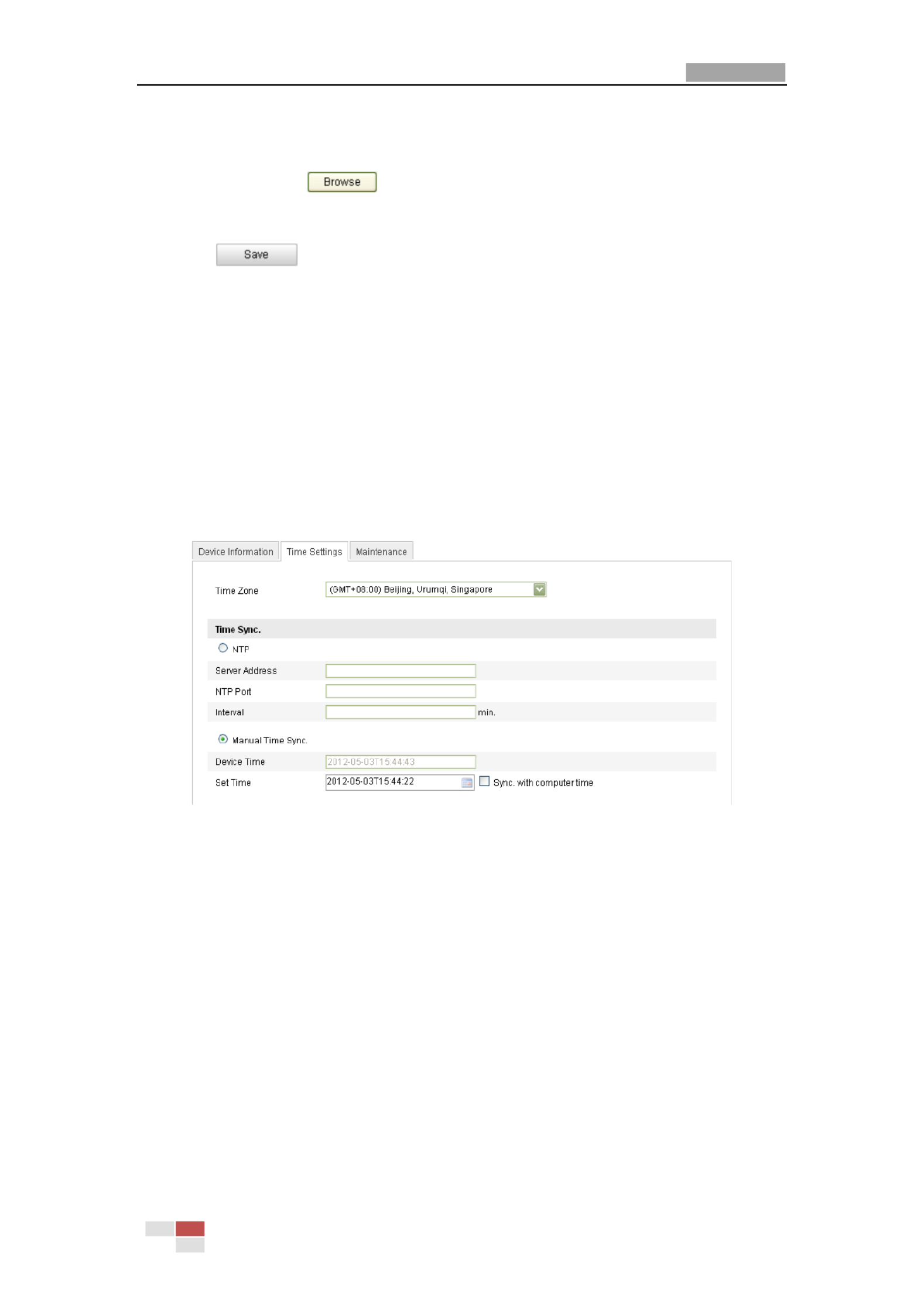
Figure 6-2 Time Settings
Select the Time Zone.
Select the Time Zone which is the closest to the location of the camera from the
drop-down menu.
Synchronizing Time by NTP Server.
(1) Check the checkbox to enable the ction. NTP fun
(2) Configure the following settings:
Server Address: IP address of NTP server.
NTP Port: Port of NTP server.
Interval: The time interval between the two synchronizing actions with NTP
server.
User Manual of Network Camera
© Hikvision Digital Technology Co., Ltd. All Rights Reserved.
36
Figure 6-3 Time Sync by NTP Server
Note: If the camera is connected to a public network, you should use a NTP server
that has a time synchronization function, such as the server at the National Time
Center (IP Address: 210.72.145.44). If the camera is set in a customized network, NTP
software can be used to establish a NTP server for time synchronization.
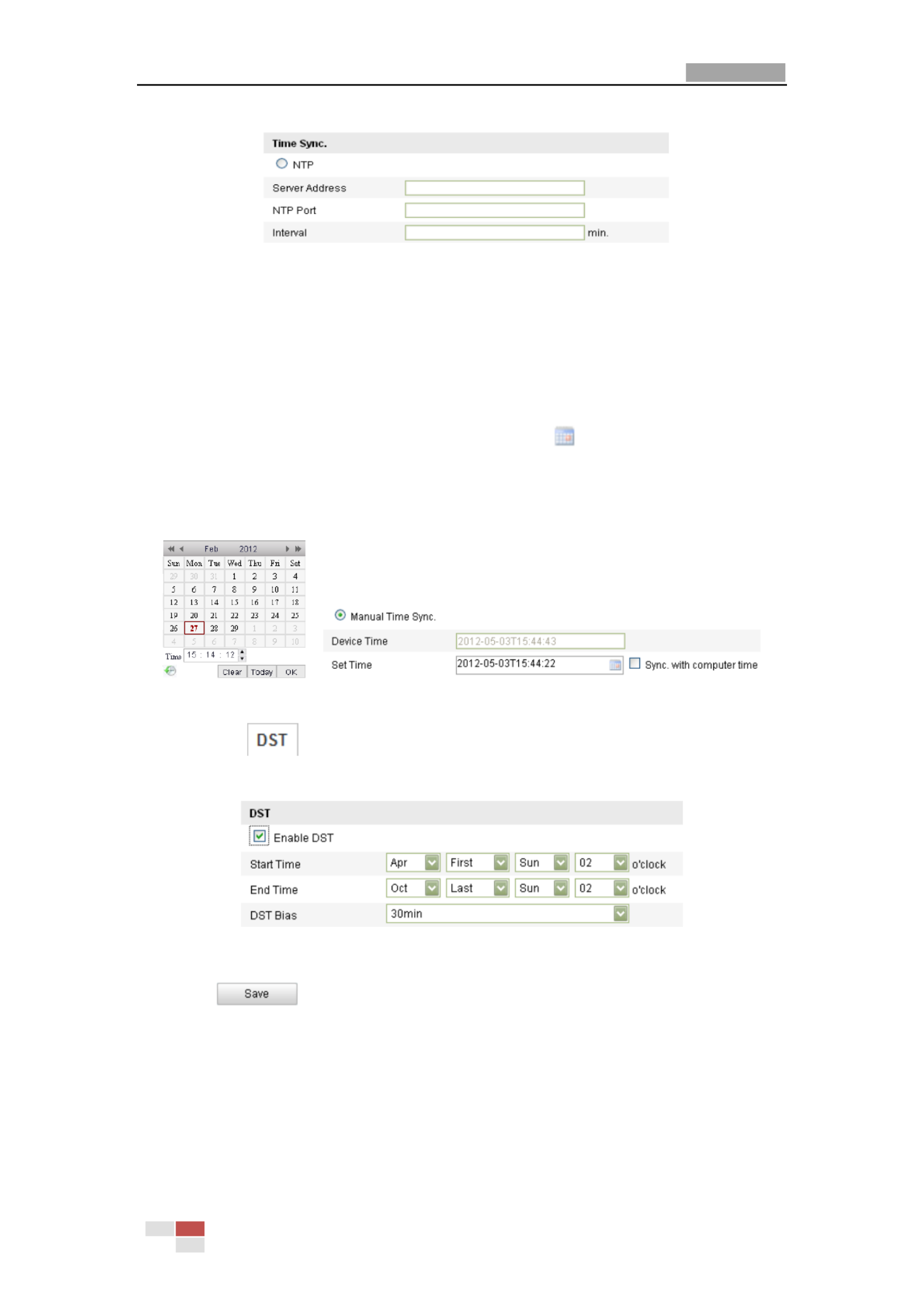
Synchronizing Time Synchronization Manually
Enable the Manual Time Sync ction and then click to set the system time fun
from the pop- calendar. up
Note: You can also check the Sync with computer time checkbox to synchronize the
time of the camera with that of your computer.
Figure 6-4 Time Sync Manually
Click the tab page to enable the DST function and Set the date of the
DST period.
Figure 6-5 DST Settings
2. Click to save the settings.

User Manual of Network Camera
© Hikvision Digital Technology Co., Ltd. All Rights Reserved.
37
6.3 Configuring Network Settings
6.3.1 Configuring TCP/IP Settings
Purpose:
TCP/IP settings must be properly configured before you operate the camera over
network. The camera supports both the IPv4 and IPv6. Both versions may be
configured simultaneously without conflicting to each other, and at least one IP
version should be configured.
Steps:
1. Enter TCP/IP Settings interface:
Configuration > Basic Configuration > twork > TCP/IP Ne
Or Configuration > Advanced Configuration > Network > TCP/IP
Figure 6-6 TCP/IP Settings
2. Configure the basic network settings, including the NIC Type, IPv4 or IPv6 Address,
IPv4 or IPv6 Subnet Mask, IPv4 or IPv6 Default Gateway, MTU settings and
Multicast Address.
Notes :
The valid value range of MTU is 500 ~ 1500.
The Multicast sends a stream to the multicast group address and allows multiple
clients to acquire the stream at the same time by requesting a copy from the
multicast group address. Before utilizing this function, you have to enable the
Multicast function of your router.

User Manual of Network Camera
© Hikvision Digital Technology Co., Ltd. All Rights Reserved.
38
3. Click to save the above settings.
Note: it will ask for a reboot for the settings to take effect.
6.3.2 Configuring Port Settings
Purpose:
You can set the port No. of the camera, e.g. HTTP port, RTSP port and HTTPS port.
Steps:
1. Enter the Port Settings interface:
Configuration > Basic Configuration > Network > Port
Or Configuration > Advanced Configuration > Network > Port
Figure 6-7 Port Settings
2. Set the HTTP port, RTSP port and HTTPS port of the camera.
HTTP Port: The default port number is 80, and can be changed to any port range
1024 to 65535.
RTSP Port: The default port number is 554.
HTTPS Port: The default port number is 443, and can be changed to any port
range 1024 to 65535.
SDK Port: The default SDK port number is 8000.
3. Click to save the settings.
Note: it will ask for a reboot for the settings to take effect.
6.3.3 Configuring PPPoE Settings
Steps:
1. Enter the PPPoE Settings interface:
Configuration >Advanced Configuration > Network > PPPoE

User Manual of Network Camera
© Hikvision Digital Technology Co., Ltd. All Rights Reserved.
39
Figure 6-8 PPPoE Settings
2. Check the checkbox to enable this feature. Enable PPPoE
3. Enter , , and password for PPPoE access. User Name Password Confirm
Note: The User Name and Password should be assigned by your ISP.
4. Click to save and exit the interface.
Note: it will ask for a reboot for the settings to take effect.
6.3.4 Configuring DDNS Settings
Purpose:
If your camera is set to use PPPoE as its default network connection, you can use the
Dynamic DNS (DDNS) for network access.
Before you start:
Registration on the DDNS server is required before configuring the DDNS settings of
the camera.
Steps:
1. Enter the DDNS Settings interface:
Configuration > Advanced Configuration > Network > DDNS
Figure 6-9 DDNS Settings
2. Check the checkbox to enable this feature. Enable DDNS

User Manual of Network Camera
© Hikvision Digital Technology Co., Ltd. All Rights Reserved.
40
3. Select . Three DDNS types are selectable: HiDDNS, IPServer and DDNS Type
DynDNS.
DynDNS:
Steps:
(1) Enter DynDNS (e.g. members.dyndns.org). Server Address of
(2) In the text field, enter the domain name obtained from the DynDNS Domain
website.
(3) Enter the of DynDNS server. Port
(4) Enter the and registered the DynDNS website. User Name Password on
(5) Click to save the settings.
Figure 6-10 DynDNS Settings
IP Server:
Steps:
(1) Enter the Server Address of the Server. IP
(2) Click to save the settings.
Note: For the IP Server, you have to apply a static IP, subnet mask, gateway and
preferred DNS from the ISP. The should be entered with the Server Address
static IP address of the computer that runs the Server software. IP
Figure 6-11 IPServer Settings
Note: For the US and Canada area, you can enter 200.91.74 as the server 173.
address.
HiDDNS
Steps:
(1) Choose the DDNS Type as HiDDNS.

User Manual of Network Camera
© Hikvision Digital Technology Co., Ltd. All Rights Reserved.
41
(2) Enter the Server Address www.hiddns.com.
(3) Enter the Domain name of the camera. The domain is the same with the
device alias in the HiDDNS server.
(4) Click to save the new settings.
Note: It will ask for a reboot for the settings to take effect.
6.3.5 Configuring SNMP Settings
Purpose:
You can set the SNMP function to get camera status, parameters and alarm related
information and manage the camera remotely when it is connected to the network.
Before you start:
Before setting the SNMP, please download the SNMP software and manage to
receive the camera information via SNMP port. By setting the Trap Address, the
camera can send the alarm event and exception messages to the surveillance center.
Note: The SNMP version you select should be the same as that of the SNMP software.
And you also need to use the different version according to the security level you
required. SNMP v1 provides no security and SNMP v2 requires password for access.
And SNMP v3 provides encryption and if you use the third version, HTTPS protocol
must be enabled.
Steps:
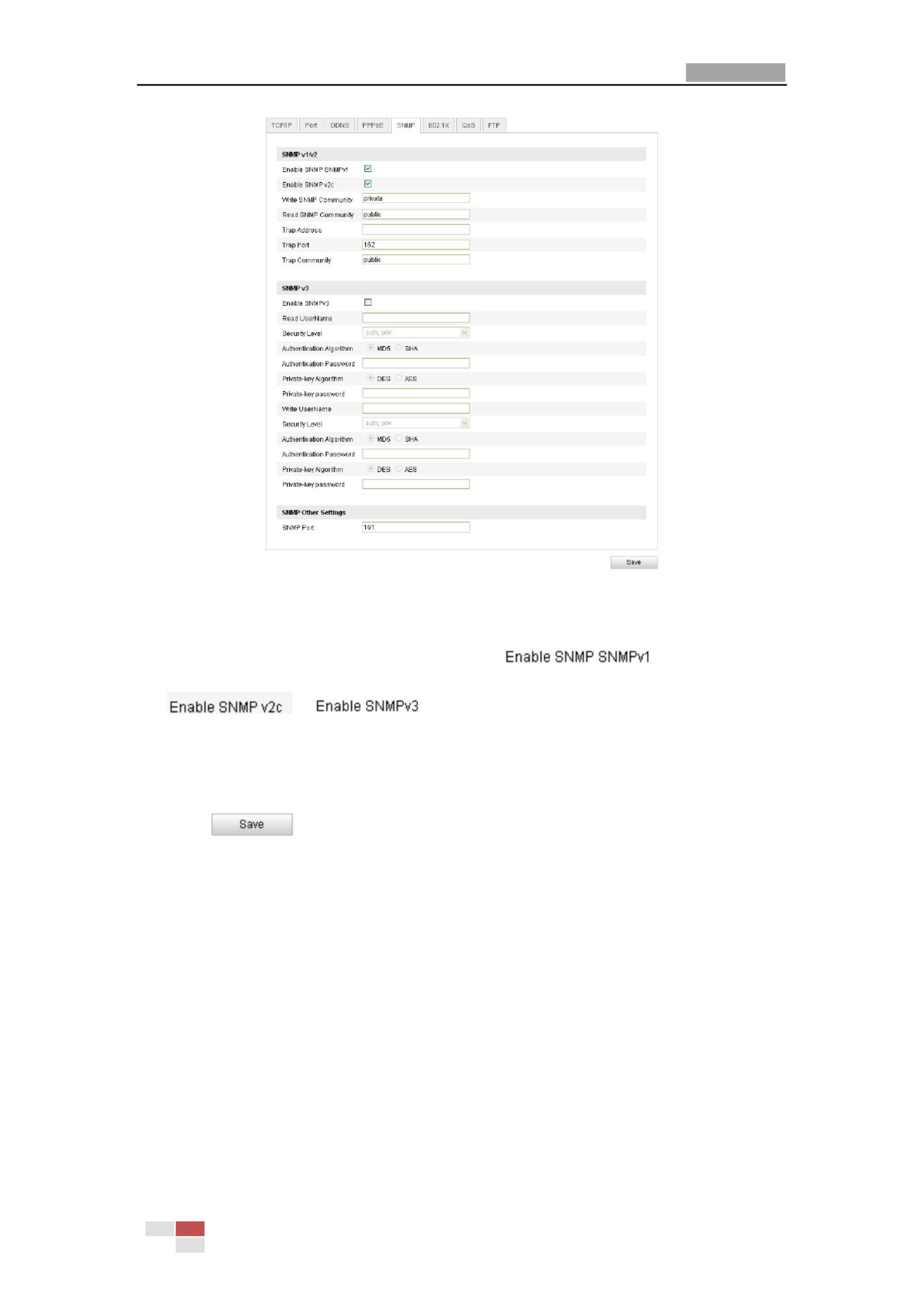
1. Enter the SNMP Settings interface:
Configuration > Advanced Configuration > Network > SNMP
User Manual of Network Camera
© Hikvision Digital Technology Co., Ltd. All Rights Reserved.
42
Figure 6-12 SNMP Settings
2. Check the corresponding version checkbox ( ,
, ) to enable the feature.
3. Configure the SNMP settings.
Note: The settings of the SNMP software should be the same as the settings you
configure here.
4. Click to save and finish the settings.
Note: it will ask for a reboot for the settings to take effect.
6.3.6 Configuring 802.1X Settings
Purpose:
The IEEE 802.1X standard is supported by the network cameras, and when the
feature is enabled, the camera data is secured and user authentication is needed
when connecting the camera to the network protected by the IEEE 802.1X.
Before you start:
The authentication server must be configured. Please apply and register a user name
and password for 802.1X in the server.
Steps:
1. Enter the 802.1X Settings interface:

User Manual of Network Camera
© Hikvision Digital Technology Co., Ltd. All Rights Reserved.
43
Configuration > Advanced Configuration > Network > 802. 1X
Figure 6-13 802.1X Settings
2. Check the checkbox to enable the feature. Enable IEEE 802.1X
3. Configure the 802.1X settings, including EAPOL version, user name and
password.
Note: The EAPOL version must be identical with that of the router or the switch.
4. Enter the user name and password to access the server.
5. Click to finish the settings.
Note: it will ask for a reboot for the settings to take effect.
6.3.7 Configuring QoS Settings
Purpose:
QoS (Quality of Service) can help solve the network delay and network congestion by
configuring the priority of data sending.
Steps:
1. Enter the QoS Settings interface:
Configuration >Advanced Configuration > Network > QoS
Figure 6-14 QoS Settings
2. Configure the QoS settings, including video / audio DSCP, event / alarm DSCP and
Management DSCP.
The valid value range of the DSCP is 0-63. The bigger the DSCP value is the higher
the priority is.
Note: DSCP refers to the Differentiated Service Code Point; and the DSCP value is
used in the IP header to indicate the priority of the data.

User Manual of Network Camera
© Hikvision Digital Technology Co., Ltd. All Rights Reserved.
44
3. Click to save the settings.
Note: it will ask for a reboot for the settings to take effect.
6.3.8 Configuring FTP Settings
Purpose:
You can configure the FTP server related information to enable the uploading of the
captured pictures to the FTP server. The captured pictures can be triggered by events
or a timing snapshot task.
Steps:
1. Enter the FTP Settings interface:
Configuration >Advanced Configuration > Network > FTP
Figure 6-15 FTP Settings
2. Configure the FTP settings; and the user name and password are required for
login the FTP server.
Directory Directory Structure: In the field, you can select the root directory,
parent directory and child directory. When the parent directory is selected, you
have the option to use the Device Name, Device Number or Device IP for the
name of the directory; and when the Child Directory is selected, you can use the
Camera Name or Camera No. as the name of the directory.
Upload type: To enable uploading the captured picture to the FTP server.
Anonymous Access to the FTP Server (in which case the user name and
password won t be requested.)’ : Check the checkbox to enable
the anonymous access to the FTP server.
Note: The anonymous access function must be supported by the FTP server.
3. Click to save the settings.
Notes: If you want to upload the captured pictures to FTP server, you have to
enable the continuous snapshot or event-triggered snapshot on page. Snapshot
For detailed information, please refer to the Section 6.6.8.

User Manual of Network Camera
© Hikvision Digital Technology Co., Ltd. All Rights Reserved.
45
6.3.9 Configuring UPnP Settings ™
Universal Plug and Play (UPnP ) is a networking architecture that provides ™
compatibility among networking equipment, software and other hardware devices.
The UPnP protocol allows devices to connect seamlessly and to simplify the
implementation of networks in the home and corporate environments.
With the function enabled, you don t need to configure the port mapping for each ’
port, and the camera is connected to the Wide Area Network via the router.
Steps:
1. Enter the UPnP settings interface. ™
Configuration >Advanced Configuration > Network > UPnP
2. Check the checkbox to enable the UPnP function. ™
The name of the device when detected online can be edited.
Figure 6-16 Configure UPnP Settings
To port mapping with the default port numbers:
Choose
To port mapping with the customized port numbers:
Choose
And you can customize the value of the port number by yourself.

User Manual of Network Camera
© Hikvision Digital Technology Co., Ltd. All Rights Reserved.
46
3. Click to save the settings.
6.4 Configuring Video and Audio Settings
6.4.1 Configuring Video Settings
Steps:
1. Enter the Video Settings interface:
Configuration >Basic Configuration > Video / Audio > Video
Or Configuration > Advanced Configuration > Video / Audio > Video
Figure 6-17 Configure Video Settings
2. Select the Stream Type of the camera to main stream (normal), sub-stream or
third stream.
The main stream is usually for recording and live viewing with good bandwidth,
and the sub-stream and third stream can be used for live viewing when the
bandwidth is limited.
3. You can customize the following parameters for the selected main stream or
sub-stream:
Video Type:
Select the stream type to video stream, or video & audio composite stream. The
audio signal will be recorded only when the Video Type Video & Audio is .
Resolution:
Select the resolution of the video output.
Bitrate Type:
Select the bitrate type to constant or variable.
Video Quality:
When bitrate type is selected , 6 levels of video quality are selectable. as Variable

User Manual of Network Camera
© Hikvision Digital Technology Co., Ltd. All Rights Reserved.
47
Frame Rate:
Set the frame rate to 1/16~25 fps. The frame rate is to describe the frequency at
which the video stream is updated and it is measured frames per second (fps). by
A higher frame rate is advantageous when there is movement in the video stream,
as it maintains image quality throughout.
Max. Bitrate:
Set the max. bitrate to 32~16384 Kbps. The higher value corresponds to the
higher video quality, but the higher bandwidth is required.
Video Encoding:
When the Stream Type of the camera is main stream, the Video Encoding
standard can be set to H.264.
When the Stream Type of the camera is sub-stream, the standard Video Encoding
can be set to H.264, MJPEG.
Profile:
Basic profile, Main Profile and High Profile for coding are selectable.
I Frame Interval:
Set the I-Frame interval to 1~400.
SVC:
Scalable video coding is an extension of the H.264/AVC standard. The technology
encodes the video signal with layers; the basic layer and several enhanced layers
and it is adaptive to the network condition to transfer different video streams For .
example, when the bandwidth is limited, only the basic layer data is encoded and
transferred. You can enable the function when you want to see the video with
several terminals, such as the mobile phone with 3G network, or the personal
computer with IP network.
4. Click to save the settings.
6.4.2 Configuring Audio Settings
Steps:
1. Enter the Audio Settings interface
Configuration > Basic Configuration > Video / Audio > Audio
Or nfiguration > Advanced Configuration > Video / Audio > AudioCo
Figure 6-18 Audio Settings
2. Configure the following settings.

User Manual of Network Camera
© Hikvision Digital Technology Co., Ltd. All Rights Reserved.
48
Audio Encoding: G.711 ulaw, G.711alaw and G.726 are selectable.
Audio Input: MicIn and Linein are selectable for the connected microphone and
pickup respectively.
3. Click to save the settings.
6.4.3 Configuring ROI Encoding
Note: Only 4-series of cameras and version above supports the function.
ROI stands for the region of interest. And the ROI encoding enables you to
discriminate the ROI and backgroun information in compression, that is to say, the d
technology assigns more encoding resource to the region of interest to increase the
quality of the ROI whereas the background information is less focused.
Steps:
1. Enter the ROI settings interface
Configuration > Advanced Configuration > Video / Audio >ROI
2. Draw the region of interest on the image. There are four regions can be drawn.
3. Choose the stream type to set the ROI encoding.
4. Choose the ROI type.
There are two options for ROI encoding, the fixed region encoding and the
dynamic tracking.
The fixed region encoding is the ROI encoding for the manually
configured area. And you can choose the Image Quality Enhancing level for
ROI encoding, and you can also name the ROI area.
And the dynamic tracking refers to the ROI defined by
intelligent analysis such as human face detection. You can choose the Image
Quality Enhancing level for the ROI encoding.
5. Click Save button to save the settings.
6.5 Configuring Image Parameters
6.5.1 Configuring Display Settings
Purpose:
You can set the image quality of the camera, including brightness, contrast,
saturation, hue, sharpness, etc.
Note: The Display parameters vary depending on the camera model.
Steps:

User Manual of Network Camera
© Hikvision Digital Technology Co., Ltd. All Rights Reserved.
49
1. Enter the Display Settings interface:
Configuration Basic Configuration> age Display Settings > Im >
Or Configuration Advanced Configuration> Image Display Settings > >
2. Set the image parameters of the camera.
Figure 6-19 Display Settings
Descriptions of parameter configuration
Overexposure Prevention: Enable or disable the function in this field.
Exposure Time:
Value ranges from 1/25 to 1/100,000s Adjust it according to the lightening condition. .
Iris Mode:
Auto and Manual are selectable.
Auto Iris Level:
If you choose the auto iris mode, you can set the auto iris level.
Video Standard:
50 Hz and 60 Hz are selectable. Choose according to the different video standards;
normally 50Hz for PAL standard and 60Hz for NTSC standard.
Day/Night Switch:
Day, Night and Auto are selectable.
Sensitivity:
If you choose auto day/night switch, you can choose the sensitivity of the switch as
high, normal and low.
Mirror
:
:
:
::
User Manual of Network Camera
© Hikvision Digital Technology Co., Ltd. All Rights Reserved.
50
The mirror function enables you to view another aspect of the image. You can flip the
image horizontally and vertically. It can be used to view the image in the way you see
it directly using your eyes.
WDR:
Wide dynamic range can be used when there is a high contrast of the bright area and
the dark area of the scene.
BLC Area:
BLC area is the area sense the light intensity; Close, Up, Down, Left, Right and Center
are selectable.
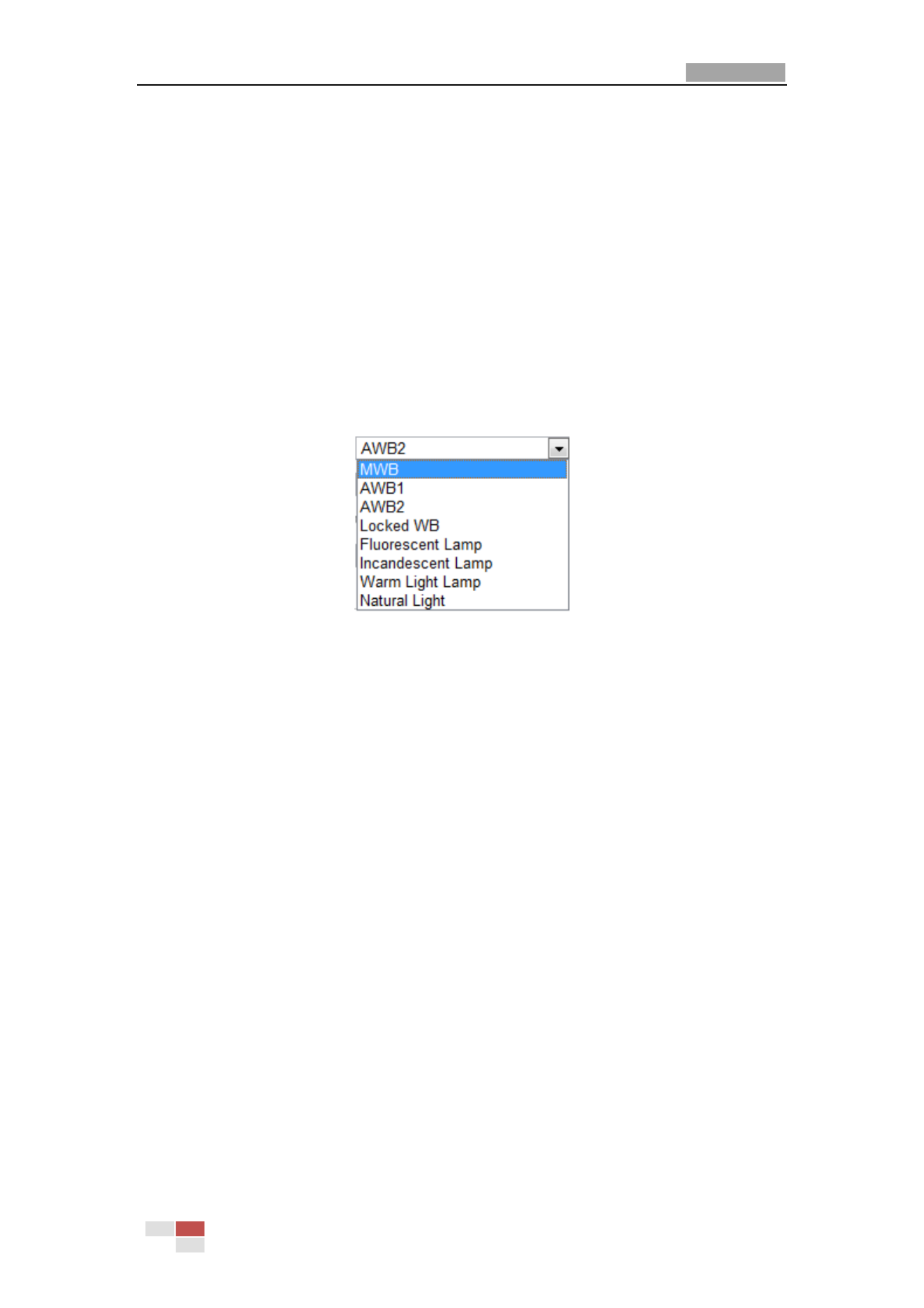
White Balance: The below figure shows the white balance type selectable. You can
choose it according to the real condition. For example, if in the surveillance scene,
there is a fluorescent lamp, you can choose the white balance type as the
Fluorescent Lamp.
Digital Noise Reduction:
Close, Normal Mode and Expert Mode are selectable.
Noise Reduction Level:
For adjusting the noise reduction level and only valid when the DNR function is
enabled.
Scene Mode:
Choose the scene as indoor or outdoor.
HLC:
High light compression function can be used when there are strong lights in the
scene which affect the image quality.
Grey Scale:
You can choose the range of the grey scale as [0-255] or [16-235].
Corridor mode:
To make a complete use of the 16:9 aspect ratio, you can enable the corridor mode
when you use the camera in a narrow view scene.
When installing, turn the camera to the 90 degrees or rotate the 3-axis lens to 90
degrees, and set the corridor mode as on, you will get a normal view of the scene
with 9:16 aspect ratio to ignore the needless information such as the wall, and get
more meaningful information of the scene.
6.5.2 Configuring OSD Settings
Purpose:

User Manual of Network Camera
© Hikvision Digital Technology Co., Ltd. All Rights Reserved.
51
You can customize the camera name and time on the screen.
Steps:
1. Enter the OSD Settings interface:
Conguraon > Advanced Conguraon > Image OSD Sengs >
Figure 6-20 OSD Settings
2. Check the corresponding checkbox to select the display of camera name, date or
week if required.
3. Edit the camera name in the text field of Camera Name.
4. Select from the drop-down list to set the time format, date format, display mode
and the OSD font size.
5. You can use the mouse to click and drag the text frame in the live
view window to adjust the OSD position.
Figure 6-21 Adjust OSD Location
6. Click to activate above settings.

User Manual of Network Camera
© Hikvision Digital Technology Co., Ltd. All Rights Reserved.
52
6.5.3 Conguring Text Overlay Setngs
Purpose:
You can customize the text overlay.
Steps:
1. Enter the Text Overlay Sengs interface:
Conguraon Advanced Conguraon > Image > Text Overlay >
2. Check the checkbox in front of textbox to enable the on-screen display.
3. Input the characters in the textbox.
4. Use the mouse to click and drag the red text frame in the live view
window to adjust the text overlay posion.
5. Click .
Note: There are up to 4 text overlays congurable.
Figure 6-22 Text Overlay Sengs
6.5.4 Conguring Privacy Mask
Purpose:
Privacy mask enables you to cover certain areas on the live video to prevent certain
spots in the surveillance area from being live view and record . ed ed
Steps:
1. Enter the Privacy Mask Sengs interface:
Conguraon Advanced Conguraon> Image > Privacy Mask >
2. Check the checkbox of Enable Privacy Mask to enable this funcon.

User Manual of Network Camera
© Hikvision Digital Technology Co., Ltd. All Rights Reserved.
53
3. Click .
Figure 6-23 Privacy Mask Sengs
4. Click and drag the mouse in the live video window to draw the mask area.
Note: You are allowed to draw up to 4 areas on the same image.
5. or Click to nish drawing click to clear all of the
areas you set without saving them.
6. Click to save the sengs.
6.5.5 Conguring Picture Overlay
Purpose:
Picture overlay enables you to overlay a picture on the image.
Steps:
1. Enter the Picture Overlay Sengs interface:
Conguraon Advanced Conguraon> Image > Picture Overlay >

User Manual of Network Camera
© Hikvision Digital Technology Co., Ltd. All Rights Reserved.
54
2. Click buon to add a picture from your PC.
3. Click buon to upload it.
4. Check the checkbox to enable the funcon.
X Coordinate and Y Coordinate values are for the locaon of the picture on the image.
And the Picture width and Height are for adjusng the size of the picture.
6.6 Conguring and Handling Alarms
Purpose:
This secon explains how to congure the network camera to respond to alarm
events, including moon detecon, external alarm input, video loss, tamper-proof
and excepon. These events can trigger the alarm acons, such as Nofy Surveillance
Center, Send Email, Trigger Alarm Output, etc.
For example, when an external alarm is triggered, the network camera sends a
nocaon to an e-mail address.
6.6.1 Conguring Moon Detecon
Purpose:
Moon detecon is a feature which can take alarm response acons and record the
video for the moon occurr in the surveillance scene. ed
Tasks:
1. Set the Moon Detecon Area.
Steps:
(1) Enter the moon detecon sengs interface
Conguraon > Advanced Conguraon> Events > Moon Detecon

User Manual of Network Camera
© Hikvision Digital Technology Co., Ltd. All Rights Reserved.
55
(2) Check the checkbox of Enable Moon Detecon.
Figure 6-24 Enable Moon Detecon
(3) Click Click and drag the mouse the live video image draw . on to a
moon detecon area.
Note: You can draw up to 8 moon detecon areas on the same image.
(4) Click to nish drawing.
Note: You can click to clear all of the areas.
(5) (Oponal) Move the slide to set the r
sensivity of the detecon.
2. Set the Arming Schedule for Moon Detecon.
Steps:

User Manual of Network Camera
© Hikvision Digital Technology Co., Ltd. All Rights Reserved.
56
Figure 6-25 Arming Time
(1) Click to edit the arming schedule. The Figure 5- shows the 28
eding interface of the arming schedule.
(2) Choose the day you want to set the arming schedule.
(3) Click to set the me period for the arming schedule.
(4) After you set the arming schedule, you can copy the schedule to other days
(Oponal).
(5) Click to save the sengs.
Note: The me of each period can’t be overlapped. Up to 4 periods can be
congured for each day.
Figure 6-26 Arming Time Schedule
3. Set the Alarm Acons for Moon Detecon.
Purpose:

User Manual of Network Camera
© Hikvision Digital Technology Co., Ltd. All Rights Reserved.
57
You can specify the linkage method when an event occurs. The following
contents are about how to congure the dierent types of linkage method.
Figure 6-27 Linkage Method
Steps:
(1) Check the checkbox to select the linkage method. Audible warning, nofy
surveillance center, send email, upload to FTP, trigger channel and trigger
alarm output are selectable (Oponal).
Audible Warning
Trigger the audible warning locally.
Nofy Surveillance Center
Send an excepon or alarm signal to remote management soware when
an event occurs.
Send Email
Send an email with alarm informaon to a user or users when an event
occurs.
Note: To send the Email when an event occurs, you need to refer to Secon
6.6.6 to set the related parameters.
Upload to FTP
Capture the image when an alarm is triggered and upload the picture to a
FTP server.
Note: Set the FTP address and the remote FTP server rst. Refer to Secon
6.3.8 for detailed informaon.
Trigger Channel
T video will be recorded when the moon is detected. You have to set the he
recording schedule to realize this funcon. Please refer to for Secon 7.2
detailed informaon.
Trigger Alarm Output
Trigger one or more external alarm outputs when an event occurs.
Note: To trigger an alarm output when an event occurs, please refer to
Secon 6.6.4 to set the related parameters.
6.6.2 Conguring Tamper-proof Alarm
Purpose:

User Manual of Network Camera
© Hikvision Digital Technology Co., Ltd. All Rights Reserved.
58
You can congure the camera to trigger the alarm when the lens is covered and take
alarm response acon.
Steps:
1. Enter the Tamper-proof Sengs interface:
Conguraon Advanced Conguraon Events > Tamper-proof > >
Figure 6-28 Tamper-proof Alarm
2. Check Enable Tamper-proof checkbox to enable the tamper-proof detecon.
3. Set the tamper-proof area; refer to Step 1 Set the Moon Detecon Area in
Secon 6.6.1.
4. Click to edit the arming schedule for tamper-proof. The arming
schedule configuraon is the same the setng of the arming schedule for moon as
detecon. Refer to in Step 2 Set the Arming Schedule for Moon Detecon Secon
6.6.1.
5. Check the checkbox to select the linkage method taken for the tamper-proof.
Audible warning, nofy surveillance center, send email and trigger alarm output are
selectable. Please refer to Step 3 Set the Alarm Acons for Moon Detecon in
Secon 6.6.1.
6. Click to save the sengs.

User Manual of Network Camera
© Hikvision Digital Technology Co., Ltd. All Rights Reserved.
59
6.6.3 Conguring External Alarm Input
Steps:
1. Enter the Alarm Input Setngs interface:
Conguraon Advanced Conguraon> Events > Alarm Input: >
2. Choose the alarm input No. and the Alarm Type. The alarm type can be NO
(Normally Open) and NC (Normally Closed). Edit the name to set a name for the
alarm input (oponal).
Figure 6-29 Alarm Input Sengs
3. Click to set the arming schedule for the alarm input. Refer to Step 2
Set the Arming Schedule for Moon Detecon in Secon 6.6.1.
4. Check the checkbox to select the linkage method taken for the alarm input. Refer
to Step 3 Set the Alarm Acons for Moon Detecon in Secon 6.6.1.
5. You can also choose the PTZ linking for the alarm input if your camera is installed
with a pan/lt unit. eck the relative checkbox and select the No. to enable Ch
Preset Calling, Patrol Calling Paern Calling. or
6. You can copy your sengs to other alarm inputs.
7. Click to save the sengs.
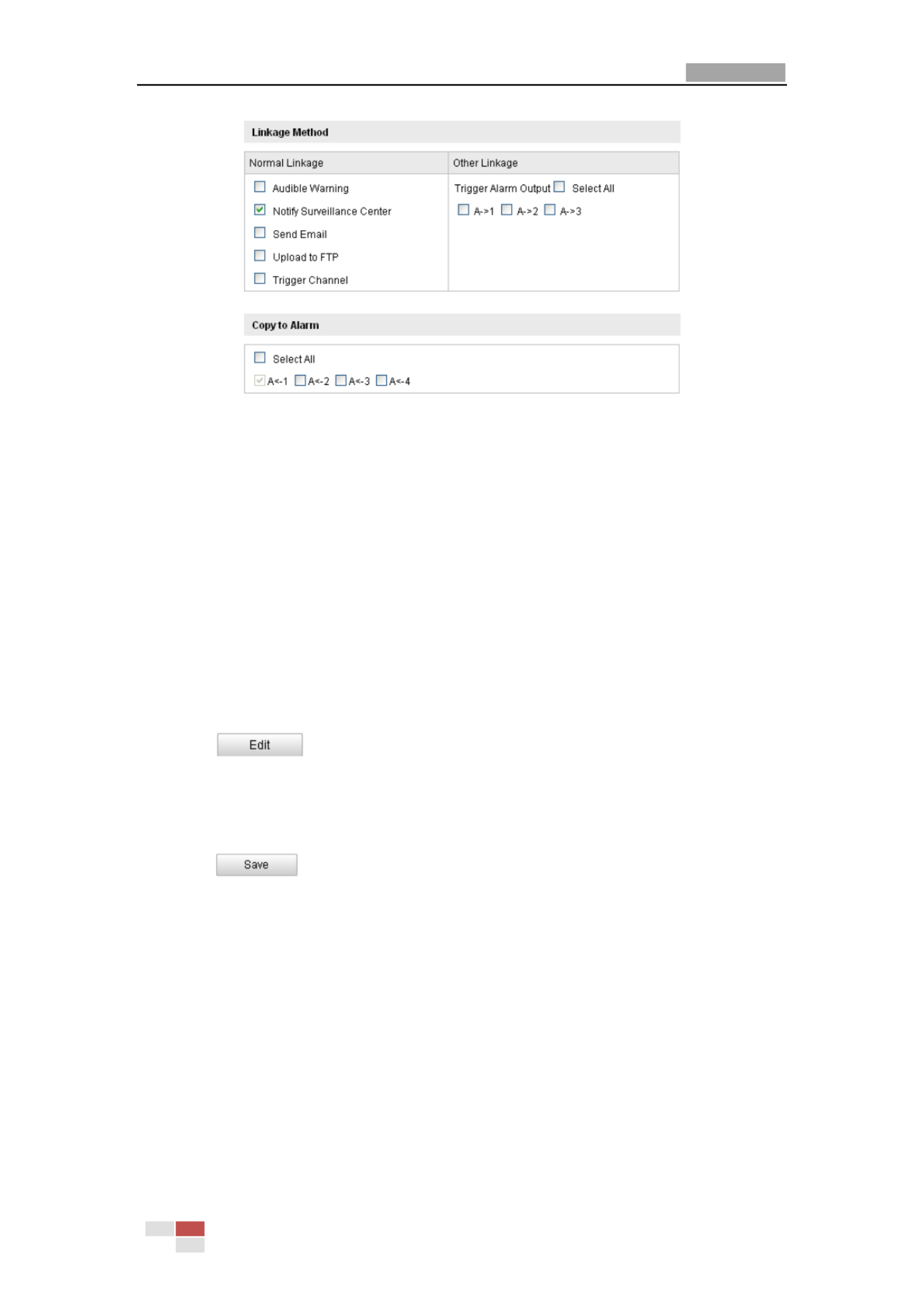
User Manual of Network Camera
© Hikvision Digital Technology Co., Ltd. All Rights Reserved.
60
Figure 6-30 Linkage Method
6.6.4 Conguring Alarm Output
Steps:
1. Enter the Alarm Output Sengs interface:
Conguraon>Advanced Conguraon> Events > Alarm Output
2. Select one alarm output channel in the drop-down list. You can Alarm Output
also set a name for the alarm output (oponal).
3. The me can be set to Delay 5sec, 10sec, 30sec, 1min, 2min, 5min, 10min or
Manual. The delay me refers to the me duraon that the alarm output remains in
effect after alarm occurs.
4. Click to enter the Edit Schedule Time interface. The me schedule
conguraon is the same the setng of the arming schedule for moon detecon as s
Refer to Step 2 Set the Arming Schedule for Moon Detecon in Secon 6.6.1.
5. You can copy the settings to other alarm outputs.
6. Click to save the sengs.
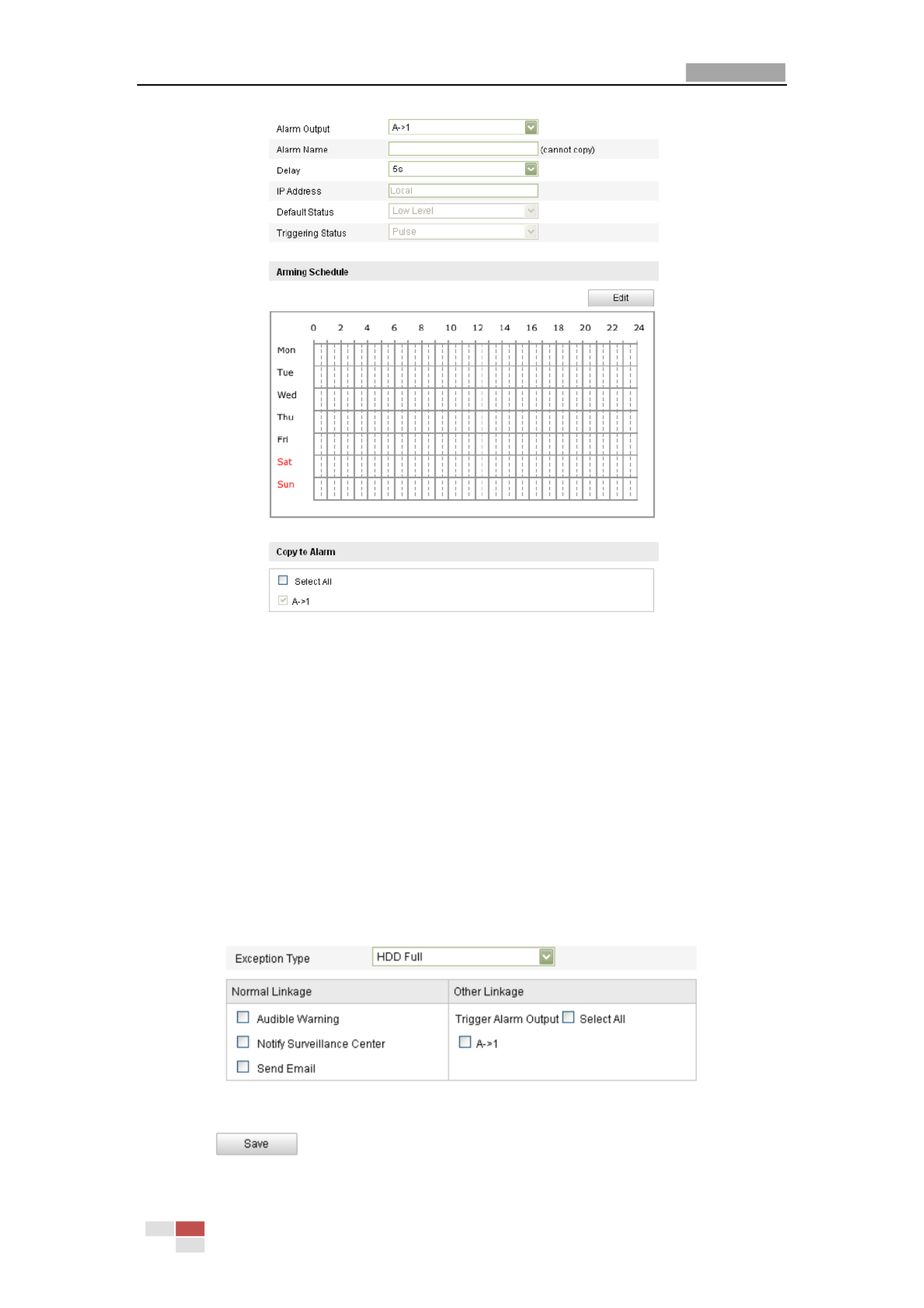
User Manual of Network Camera
© Hikvision Digital Technology Co., Ltd. All Rights Reserved.
61
Figure 6-31 Alarm Output Setngs
6.6.5 Handling Excepon
The excepon type can be HDD full, HDD error, network disconnect , IP address ed
conict and illegal login to the cameras. ed
Steps:
1. Enter the Excepon Sengs interface:
Conguraon > Advanced Conguraon> Events > Excepon
2. Check the checkbox to set the acons taken for the Excepon alarm. Refer to
Step 3 Set the Alarm Acons Taken for Moon Detecon in Secon 6.6.1.
Figure 6-32 Excepon Sengs
3. Click to save the setngs.

User Manual of Network Camera
© Hikvision Digital Technology Co., Ltd. All Rights Reserved.
62
6.6.6 Email Sending Triggered by Alarm
Purpose:
The system can be congured to send an Email noficaon to all designated
receivers if an alarm event is detected, e.g., moon detecon event, video loss,
tamper-proof, etc.
Before you start:
Please congure the DNS Server sengs under Basic Conguraon > Network >
TCP/IP Advanced Conguraon > Network > TCP/IPor before using the Email
funcon.
Steps:
1. Enter the TCP/IP Sengs (Conguration > Basic Conguraon > Network > TCP/IP or
Conguraon > Advanced Conguraon > Network > TCP/IP ) to set the IPv4
Address, IPv4 Subnet Mask, IPv4 Default Gateway and the Preferred DNS Server.
Note: Please refer to for detailed Conguring TCP/IP SengsSecon 6.3.1
informaon.
2. Enter the Email Setngs interface:
Conguraon > Advanced Configuraon > Events > Email
Figure 6-33 Email Sengs
3. Congure the following sengs:
Sender: The name of the email sender.
Sender’s Address: The email address of the sender.
SMTP Server: The SMTP Server IP address or host name (e.g.,
smtp.263xmail.com).
SMTP Port: The SMTP port. The default TCP/IP port for SMTP is 25 (not secured).

User Manual of Network Camera
© Hikvision Digital Technology Co., Ltd. All Rights Reserved.
63
And the SSL SMTP port is 465.
Enable SSL: Check the checkbox to enable SSL if it is required by the SMTP
server.
Aached Image: Check the checkbox of Aached Image if you want to send
emails with attached alarm images.
Interval: The interval refers to the me between two actions of sending attached
pictures.
Authencaon (oponal): If your email server requires authencaon, check
this checkbox to use authencaon to log in to this server and enter the login
user Name and password.
Choose Receiver: Select the receiver to which the email is sent. Up to 2 receivers
can be congured.
Receiver: The name of the user to be noed.
Receiver’s Address: The email address of user to be noed.
4. Click to save the sengs.
6.6.7 Conguring Snapshot Sengs
Purpose:
You can congure the scheduled snapshot and event-triggered snapshot. The
captured picture can be stored in the SD card (if supported) or the netHDD (For
detailed informaon about netHDD, please refer to Secon 7.1 Conguring NAS
Sengs). You can also upload the captured pictures to a FTP server.
Basic Sengs
Steps:
1. Enter the Snapshot Setngs interface:
Conguraon > Advanced Conguraon > Events > Snapshot
2. Check the checkbox to enable connuous snapshot. Enable Timing Snapshot
Check the Enable Event-triggered Snapshot checkbox to check event-triggered
snapshot.
3. Select the quality of the snapshot.
4. Set the me interval between two snapshots.
5. Click to save the sengs.
Uploading to FTP
You can follow below conguration instrucons to upload the snapshots to FTP.
Upload connuous snapshots to FTP
Steps:
1) Congure the FTP setngs and check checkbox in FTP
Sengs interface Please refer to for more . Secon 6.3.8 Conguring FTP Sengs
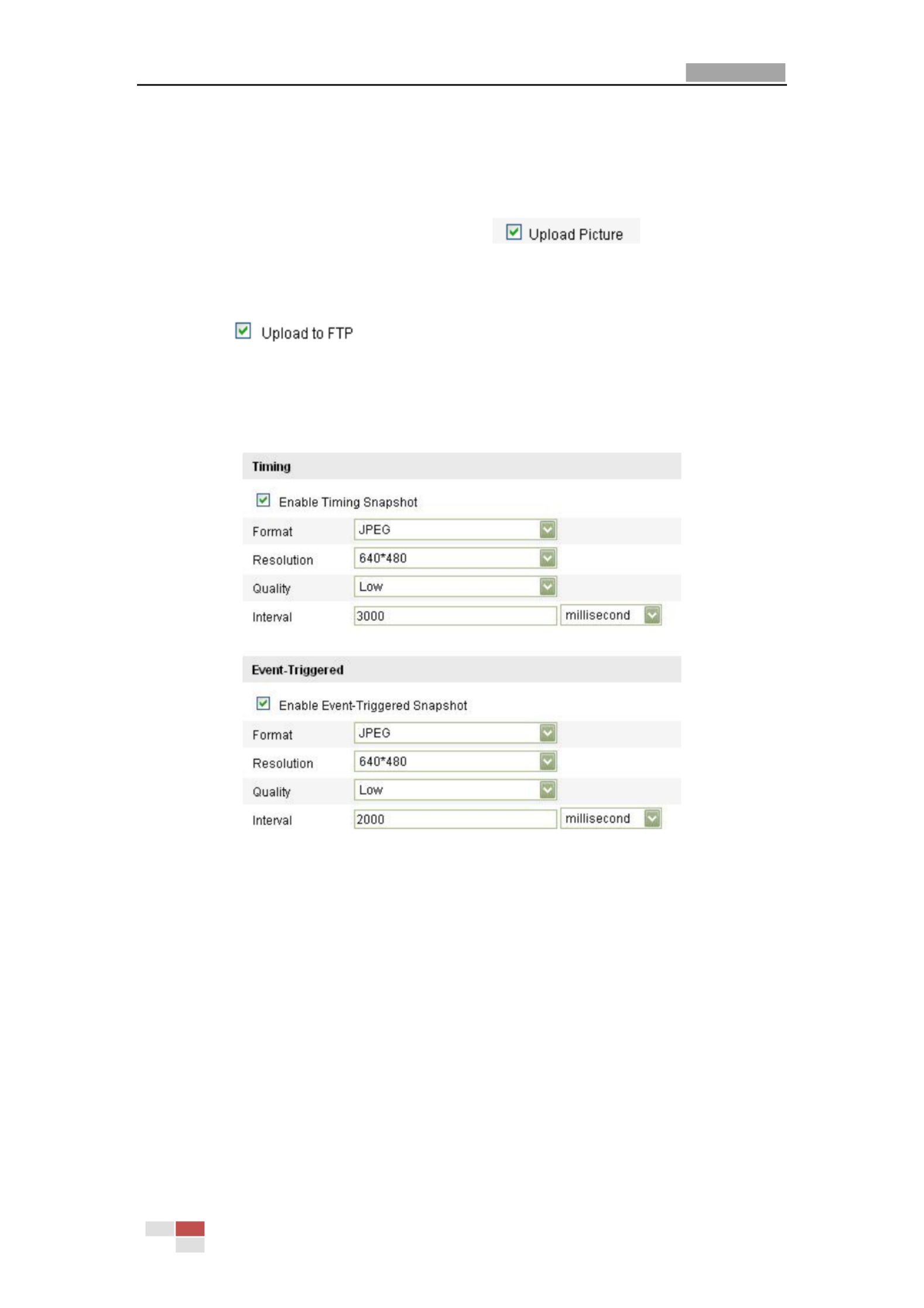
User Manual of Network Camera
© Hikvision Digital Technology Co., Ltd. All Rights Reserved.
64
details to congure FTP parameters.
2) Check the Enable Timing Snapshot checkbox.
Upload event-triggered snapshots to FTP
Steps:
1) Congure the FTP setngs and check checkbox in FTP
Sengs interface Please refer to for more . Secon 6.3.8 Conguring FTP Sengs
details to congure FTP parameters.
2) Check checkbox in Moon Detecon Sengs or Alarm Input
interface. Please refer to Step 3 Set the Alarm Acons Taken for Moon
Detecon Conguring External Alarm Input in Secon 6.6.1, or Step 4 in Secon
6.6.4.
3) Check the Enable Event-triggered Snapshot checkbox.
Figure 6-34 Snapshot Sengs
6.6.8 Face Detection
Note: Face detecon is only for certain modules, check the specicaon for whether
the module supports the funcon.
If you enable the face detecon, once a face appears in the surveillance area, it will
be detected and certain acons may be triggered by the detecon.

User Manual of Network Camera
© Hikvision Digital Technology Co., Ltd. All Rights Reserved.
65
Steps:
1. Enter the face detecon sengs interface:
Conguraon > Advanced Conguraon > Events > Face Detecon
2. Check the Enable Face Detecon to checkbox to enable the funcon.
3. (Oponal)You can check the Enable Dynamic Analysis for Face Detection
checkbox if you want the face detect get marked with rectangle in the live ed
view.
4. Congure the sensivity of face detecon. The default value is 5.
5. (Oponal)You can also congure the linkage acon for face detecon.
6.6.9 Configuring Other Alarms
Purpose:
This secon is for the camera supporng external wireless alarm (e.g. access control
alarm), embedded PIR (passive infrared sensor) alarm and manual alarm by remote
control.
Study the wireless alarm and the remote control
Purpose:
The wireless alarm is the funcon of the camera to communicate to wireless alarm
devices such as the access control. The remote control or other remote alarm devices
must be compable and learn each other’s remote signal to communicate.
Before congure the wireless alarm, the camera must study the code of the wireless
alarm device.
Steps:
1. Enter the Remote Control interface:
Conguraon> Advanced Conguraon> System Remote Control >

User Manual of Network Camera
© Hikvision Digital Technology Co., Ltd. All Rights Reserved.
66
Figure 6-35 Remote Control Sengs
2. Study the code of the remote control or the wireless alarm.
To study a remote control, select Remote Control from the Study drop-down list, and
click ; and then press any of the buttons on the remote control against the
camera to send the signal.

User Manual of Network Camera
© Hikvision Digital Technology Co., Ltd. All Rights Reserved.
67
Remote Control:
Figure 6-36 Remote Control
Remote Control Descripon:
Status Indicator
Indicang the status of the remote; when
you press the buon on the remote, the
indicator icks in red.
Arm
Press the buon to arm the camera. In
arming status, the alarm funcon, such
as the wireless alarm and the PIR alarm,
is enabled.
Disarm
Press the buon to disarm the camera. In
the disarming status, the alarm linkage is
disabled.
Emergency Buon
Press the buon to trigger the
emergency alarm. The emergency alarm
has the highest priority.
Stream Sending Switch
Switch for the video stream transmitng.
Press the buon to stop or start video
stream sending. When the video stream
is stopped, you can t see the live view or ’
get the record stream on the remote
client or browser.

User Manual of Network Camera
© Hikvision Digital Technology Co., Ltd. All Rights Reserved.
68
To study the wireless alarms, e.g. the access control device, select Wireless
Alarm Study from the drop-down list, and select the device serial number (1-8)
from the drop-down list, and click and then send the signal from the ;
wireless alarm device to the camera .
Figure 6-37 Study the Wireless Alarm
No s: te
To study the access control device, you can open the door/separate the device to
send the signal.
Congure Wireless Alarm and PIR Alarm the
Congure the Wireless Al arm
Steps:
(1) Enter the Wireless Alarm Setngs interface:
Conguraon > Advanced Conguraon > Events > Other Alarm
(2) Select the wireless alarm number. This camera supports up to 8 channels of
external wireless alarm input.
Figure 6-38 Wireless Alarm Setngs
(3) Check the checkbox of to acvate the alarm and dene Enable Wireless Alarm
the alarm name in the eld. Alarm Name
(4) Check the checkbox to select the linkage method taken for the wireless alarm .
Audible warning, nofy surveillance center, send email, upload to FTP, trigger
channel, trigger alarm output and trigger wireless alarm output are selectable.
Please refer to Step 3 Set the Alarm Actions for Moon Detecon Secon in
6.6.1.

User Manual of Network Camera
© Hikvision Digital Technology Co., Ltd. All Rights Reserved.
69
Note: DS-2CD8464F-EI(Z)(W) camera supports wireless audible and visual alarm as
the wireless alarm output for the wireless alarm. Check the check box of Wireless
audible and visual alarm to acvate the alarm output.
Figure 6-39 Wireless Alarm Output
(5) Click to save the sengs.
Congure the PIR Alarm
Steps:
(1) In the Other Alarm conguraon interface, check the checkbox of Enable PIR
Alarm to acvate the PIR alarm and dene the alarm name in the Alarm Name
eld.
Figure 6-40 PIR Alarm Settings
(2) Check the checkbox to select the linkage method taken for the PIR alarm Audible .
warning, nofy surveillance center, send email, upload to FTP, trigger channel,
trigger alarm output and trigger wireless alarm output are selectable. Please
refer to Step 3 Set the Alarm Acons for Moon Detecon Secon 6.6.1.in
Note: DS-2CD8464F-EI camera supports wireless audible and visual alarm as the
wireless alarm output for the PIR alarm. Check the check box of Wireless audible
and visual alarm to acvate the alarm outp ut.
Figure 6-41 Wireless Alarm Output
(3) Click to save the sengs.
Note: The wireless alarm/PIR alarm triggered record will be started if the wireless
alarm or PIR alarm is triggered on the dened recording schedule, either when the
wireless/PIR alarm is enabled or not. Please refer to Secon 7.2 for details about
conguring recording schedule.

User Manual of Network Camera
© Hikvision Digital Technology Co., Ltd. All Rights Reserved.
70
Manual Alarm/Emergency Alarm
Certain series of camera support manual alarm by the remote control. It can be
manually triggered and linked to the audio warning if any emergency happens. You
can press and hold the manual alarm buon on the remote control for 2 seconds to
trigger the audio warning manually.
Notes :
The manual alarm is enabled and armed by default and not user-congurable.
The manual alarm triggered record will be started if the manual alarm is
triggered on the dened recording schedule, and will be stopped in 10 seconds
aer the manual alarm stops. Please refer to for details about Secon 7.2
conguring recording schedule.
6.6.10 Arming or Disarming the Camera
Purpose:
This secon is for camera support the funcon only. You can follow below steps to
congure all-day arming for the camera with the wireless alarm, PIR alarm, moon
detecon, tamper-proof, etc.
Notes :
Emergency alarm is enabled and armed by default and not included in this secon.
The arming and disarming funcon can also be realized by the remote control.
Arm the camera
Steps:
1. Enter the Remote Control interface:
Conguraon> Advanced Conguraon> System Remote Control >
2. Select from the drop-down list. Arm Arm/Disarm
3. Set the arming delay.
Note: Arming delay refers to a me delay to arm the camera aer you set it to
arming status on this page. You can set the delay as 10 seconds, 30 seconds, 1 minute,
3 minutes or 5 minutes. You can also customize the delay me.
Figure 6-42 Arm the Camera
4. Click to arm the camera.
Disarm the camera
In the Remote Control interface, select from the drop-down list Disarm Arm/Disarm
and click to disarm the camera.
Notes:

User Manual of Network Camera
© Hikvision Digital Technology Co., Ltd. All Rights Reserved.
71
You can also press the Arm/Disarm buon on the remote control to arm/disarm
the camera if the camera has already studied the remote control.
The arming indicator glows red when the camera is armed and glows blue when
it’s disarmed.

User Manual of Network Camera
72
Chapter 7 Storage Setngs
Before you start:
To configure record settings, please make sure that you have the network storage
device within the network or the SD card inserted in your camera.
7.1 Conguring N Setngs AS
Before you start:
The network disk should be available within the network and properly configured to
store the recorded files, log files, etc.
Steps:
1. Add the network disk
(1) Enter the NAS (Network-Attached Storage) Settings interface:
Conguraon > Advanced Configuration > Storage > NAS
Figure 7-1 Add Network Disk
(2) Enter the IP address of the network disk, and enter the default file.
Note: Please refer to the User Manual of NAS for creating the file path.
(3) Click to add the network disk.
Note: After having saved successfully, you need to reboot the camera to activate
the settings.
2. Initialize the added network disk.
(1) Enter the HDD Settings interface ( Advanced Conguraon > Storage >
Storage Management), in which you can view the capacity, free space, status,
type and property of the disk.
Figure 7-2 Initialize Disk
(2) If the status of the disk is Uninialized, check the corresponding checkbox to
select the disk and click to start initializing the disk.

User Manual of Network Camera
© Hikvision Digital Technology Co., Ltd. All Rights Reserved.
73
Figure 7-3 Initializing
When the initialization completed, the status of disk will become Normal.
Figure 7-4 View Disk Status
Notes :
Up to 8 NAS disks can be connected to the camera.
To initialize and use the SD card after insert it to the camera, please refer to the
steps of NAS disk initialization.
7.2 Configuring Recording Schedule
Purpose:
There are two kinds of recording for the cameras: manual recording and scheduled
recording. For the manual recording, refer to Section 5.3 Recording and Captu ng ri
Pictures Manually. In this section you can follow the instructions to configure the ,
scheduled recording. By default, the record files scheduled recording are stored in of
the SD card (if supported) or in the network disk.
Steps:
1. Enter the Record Schedule Settings interface:
Configuration Advanced Configuration> Storage > Record Schedule >

User Manual of Network Camera
© Hikvision Digital Technology Co., Ltd. All Rights Reserved.
74
Figure 7-5 Recording Schedule Interface
2. Check the checkbox of Enable Record Schedule to enable schedule recording. d
3. Set the record parameters of the camera.
Figure 7-6 Record Parameters
Pre-record: The time you set to start recording before the scheduled time or
the event. For example, if an alarm triggers recording at 10:00, and the
pre-record time is set as 5 seconds, the camera starts to record at 9:59:55.
The Pre-record time can be configured as No Pre-record, 5 s, 10 s, 15 s, 20 s,
25 s, 30 s or not limited.
Post-record: The time you set to stop recording after the scheduled time or
the event. For example, an alarm trigger recording ends at 11:00, and the if ed
post-record time is set as 5 seconds, the camera records until 11:00:05.
The Post-record time can be configured as 5 s, 10 s, 30 s, 1 min, 2 min, 5 min
or 10 min.
Note: The record parameter configurations vary depending on the camera model.
4. Click to edit the record schedule.

User Manual of Network Camera
© Hikvision Digital Technology Co., Ltd. All Rights Reserved.
75
Figure 7-7 Record Schedule
5. Choose the day set the record schedule. to
(1) Set all-day record or segment record:
If you want to configure the all-day recording, please check the All Day
checkbox.
If you want to record in different time sections, check the Customize
checkbox. Set the and Start Time End Time.
Note: The time of each segment can’t be overlapped. Up to 4 segment can s
be configured.
(2) Select a Record Type. The record type can be Normal, Motion Detection,
Alarm, Motion | Alarm, Motion & Alarm, PIR Alarm, Wireless Alarm,
Emergency Alarm, or Motion | Alarm Input | PIR | Wireless | Emergency.
Normal
If you select video will be recorded automatically according to Normal, the
the time of the schedule.
Record Triggered by Motion Detection
If you select Motion Detection, the video will be recorded when the
motion is detected.
Besides configuring the recording schedule, you have to set the motion
detection area and check the checkbox of Trigger Channel Linkage in the
Method of Motion Detection Settings interface. For detailed information,
please refer to the Step 1 Set the Motion Detection Area in the Section
5.6.1.
Record Triggered by Alarm
If you select the video will be recorded when the alarm is triggered Alarm,
via the external alarm input channels.
Besides configuring the recording schedule, you have to set the Alarm Type
and check the checkbox of Trigger Channel Linkage Method in the of
Alarm Input Settings interface. For detailed information, please refer to

User Manual of Network Camera
© Hikvision Digital Technology Co., Ltd. All Rights Reserved.
76
Section 5.6.4 .
Record Triggered by Motion Alarm &
If you select Motion Alarm& , the video will be recorded when the motion
and alarm are triggered at the same time.
Besides configuring the recording schedule, you have to configure the
settings on the Motion Detection Alarm Input Settings and interfaces.
Please refer to and for detailed informationSection 5.6.1 Section 5.6.4 .
Record Triggered by Motion | Alarm
If you select , Motion | Alarm the video will be recorded when the external
alarm is triggered or the motion is detected.
Besides configuring the recording schedule, you have to configure the
settings on the Motion Detection Alarm Input Settings and interfaces.
Please refer to and for detailed informationSection 5.6.1 Section 5.6.4 .
Record Triggered by PIR A larm
If you select PIR Alarm, video will be recorded when the PIR alarm is the
detected.
Besides configuring the recording schedule, you have to set the PIR alarm
and check the checkbox of Trigger Channel Normal Linkage in the of PIR
Alarm in Other Alarm Settings interface. For detailed information, please
refer to Step 2 in the Section 5.6.9. Configure the PIR Alarm
Record Triggered by Wireless Alarm
If you select Wireless Alarm, video will be recorded when the wireless the
alarm is detected.
Besides configuring the recording schedule, you have to set the wireless
alarm and check the checkbox of Trigger Channel Normal Linkage in the of
Wireless Alarm in Other Alarm Settings interface. For detailed information,
please refer to Step 1 in the Section 5.6.9. Configure the Wireless Alarm
Record Triggered by Emergency Alarm
If you select Emergency Alarm, the video will be recorded when the
emergency alarm is detected.
Note: This type is for certain series camera only.
Record Triggered by Manual Alarm
If you select , video will be recorded when manual alarm Manual Alarm the
is triggered.
Record Triggered by PIR | Wireless | Manual
If you select PIR | Wireless | Manual, the video will be recorded when the
PIR alarm or wireless alarm or manual alarm is detected.
Besides configuring the recording schedule, you have to configure the
settings for wireless alarm and PIR alarm in Other Alarm Settings interface.
For detailed information, please refer to Section 5.6.9.

User Manual of Network Camera
© Hikvision Digital Technology Co., Ltd. All Rights Reserved.
79
process.
Figure 8-3 Playback Toolbar
Table 8-1 Description of the buttons
Button
Operation
Button
Operation
Play
Capture a picture
Pause
/
Start/Stop clipping video
files
Stop
/
Audio on and adjust
volume/Mute
Speed down
Download video files
Speed up
Download captured
pictures
Playback by
frame
/
Enable/Disable digital
zoom
Note: You can choose the file paths locally for downloaded playback video files and
pictures in Local Configuration interface. Please refer to for details. Section 5.1
Drag the progress bar with the mouse to locate the exact playback point. You can
also input the time and click to locate the playback point in the Set playback
time field. You can also click to zoom out/in the progress bar.
Figure 8-4 Set Playback Time
Figure 8-5 Progress Bar
The different colors of the video on the progress bar stand for the different video
types.
Figure 8-6 Video Types

User Manual of Network Camera
80
Chapter 9 Log Searching
Purpose:
The operation, alarm, exception and information of the camera can be stored in log
files. You can also export the log files on your demand.
Before you start:
Please configure network storage for the camera or insert a SD card in the camera.
Steps:
1. Click on the menu bar to enter log searching interface.
Figure 9-1 Log Searching Interface
2. Set the log search conditions to specify the search, including the Major Type,
Minor Type, Start Time and End Time.
3. Click to search log files. The matched log files will be displayed on
the interface. Log
Figure 9-2 Log Searching
4. To export the log files, click to save the log files your computer. in

User Manual of Network Camera
81
Chapter 10 Others
10.1 Managing User Accounts
Enter the User Management interface:
Configuration >Basic Configuration> Security > User
O Configuration > Advanced Configuration> Security > User r
The user has access to create, modify or delete other accounts. Up to 15 user admin
accounts can be created.
Figure 10-1 User Information
Add User a
Steps:
1. Click to add a user.
2. Input the new User Name Level Password., select and input
Note: The level indicates the permissions you give to the user. You can define the
user as Operator User or .
3. In the Basic Permission Camera Configuration field and field, you can check or
uncheck the permissions for the new user.
4. Click to finish the user addition.

User Manual of Network Camera
© Hikvision Digital Technology Co., Ltd. All Rights Reserved.
82
Figure 10-2 Add a User
Modify User a
Steps:
1. Left-click to select the user from the list and click .
2. Modify the User Name Level Password, or .
3. In the Basic Permission Camera Configuration field and field, you can check or
uncheck the permissions.
4. Click to finish the user modification.
Figure 10-3 Modify User a

User Manual of Network Camera
© Hikvision Digital Technology Co., Ltd. All Rights Reserved.
83
Delete a User
Steps:
1. Left- ick the user name you want to delete and click . cl
2. Click on the pop-up dialogue box to delete the user.
Figure 10-4 Delete a User
Anonymous Visit
10.2 Configuring RTSP Authentication
Purpose:
You can specifically secure the stream data of live view.
Steps:
1. Enter the RTSP Authentication interface:
Configuration> Advanced Configuration> Security > RTSP Authentication
Figure 10-5 RTSP Authentication
2. Select the Authentication basic disable type or in the drop-down list to enable
or disable the RTSP authentication.
Note: If you disable the RTSP authentication, anyone can access the video stream by
the RTSP protocol via the IP address.
3. Click to save the settings.
10.3 Anonymous Visit
Purpose:
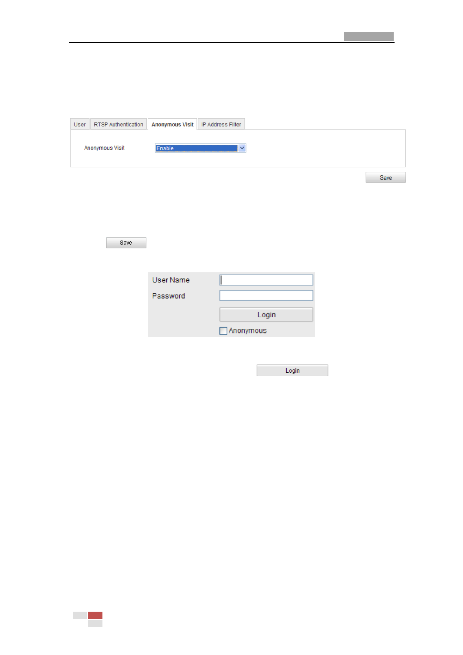
User Manual of Network Camera
© Hikvision Digital Technology Co., Ltd. All Rights Reserved.
84
Enabling this function allows visit for whom doesn t have the user name and ’
password of the device.
Steps:
1. Enter the Anonymous Visit interface:
Configuration> Advanced Configuration> Security > Anonymous Visit
Figure 10-6 Anonymous Visit
2. Set the Anonymous Visit Enable Disable permission or in the drop-down list to
enable or disable the anonymous visit.
3. Click to save the settings.
There will be a checkbox of Anonymous by the next time you logging in.
Figure 10-7 Login Interface with an Anonymous Checkbox
4. Check the checkbox of and click . Anonymous
10.4 IP Address Filter
Purpose:
This function makes it possible for access control.
Steps:
1. Enter the IP Address Filter interface:
Configuration> Advanced Configuration> Security > IP Address Filter

User Manual of Network Camera
© Hikvision Digital Technology Co., Ltd. All Rights Reserved.
85
Figure 10-8 IP Address Filter Interfa ce
2. Check the checkbox of Enable IP Address Filter.
3. Select the type of IP Address Filter in the drop-down list, and Forbidden Allowed
are selectable.
4. Set the IP Address Filter list.
Add an IP Address
Steps:
(1) Click the button to add an IP.
(2) Input the IP Adreess.
Figure 10-9 Add an IP
(3) Click the button to finish adding.
Modify an IP Address
Steps:
(1) Left-click an IP address from filter list and click button.
(2) Modigy the IP address in the text filed.
Specyfikacje produktu
| Marka: | Hikvision |
| Kategoria: | Kamera monitorująca |
| Model: | DS-2CD8283F-EIZ |
| Kolor produktu: | Biały |
| Liczba źródeł światła: | 2 szt. |
| Rodzaj żarówki: | LED |
| Typ kontroli: | Dotyk |
| Wbudowany wyświetlacz: | Tak |
| Częstotliwość wejściowa AC: | 50 Hz |
| Napięcie wejściowe AC: | 220 - 240 V |
| Szerokość produktu: | 600 mm |
| Głębokość produktu: | 351 mm |
| Waga produktu: | 13600 g |
| Szerokość opakowania: | 690 mm |
| Wysokość opakowania: | 480 mm |
| Głębokość opakowania: | 400 mm |
| Poziom hałasu: | 60 dB |
| Klasa wydajności energetycznej: | A |
| Skala efektywności energetycznej: | A +++ do D |
| Waga wraz z opakowaniem: | 15500 g |
| Lampy: | 1 W |
| Model: | Naścienny |
| Roczne zużycie energii: | 32 kWh |
| Prędkości: | 3 |
| Maksymalna moc ekstrakcji: | 405 m³/h |
| Rodzaj ekstrakcji: | Kanałowe / obiegowe |
| Klasa wydajności przepływu dynamicznego: | B |
| Klasa wydajności świecenia: | A |
| Klasa skuteczności filtra przeciwtłuszczowego: | E |
| Poziom hałasu (niska prędkość): | 52 dB |
| Rodzaj filtra tłuszczu: | Metal/węgiel |
| Zdjemowalny filtr: | Tak |
| Wysokość bez komina: | 343 mm |
| Silnik dołączony: | Tak |
| Ilość silników: | 1 |
| Poziom hałasu (wysoka prędkość): | 60 dB |
| Lokalizacja wydechu: | Górne |
Potrzebujesz pomocy?
Jeśli potrzebujesz pomocy z Hikvision DS-2CD8283F-EIZ, zadaj pytanie poniżej, a inni użytkownicy Ci odpowiedzą
Instrukcje Kamera monitorująca Hikvision

12 Stycznia 2025
12 Stycznia 2025
12 Stycznia 2025
12 Stycznia 2025
11 Stycznia 2025
7 Stycznia 2025
19 Grudnia 2024
19 Grudnia 2024
19 Grudnia 2024
19 Grudnia 2024
Instrukcje Kamera monitorująca
- Kamera monitorująca Sony
- Kamera monitorująca Samsung
- Kamera monitorująca Tenda
- Kamera monitorująca Motorola
- Kamera monitorująca Stabo
- Kamera monitorująca Logitech
- Kamera monitorująca Xiaomi
- Kamera monitorująca Braun
- Kamera monitorująca Pioneer
- Kamera monitorująca TP-Link
- Kamera monitorująca Philips
- Kamera monitorująca Bosch
- Kamera monitorująca Gigaset
- Kamera monitorująca EZVIZ
- Kamera monitorująca Conceptronic
- Kamera monitorująca Panasonic
- Kamera monitorująca Canon
- Kamera monitorująca Crestron
- Kamera monitorująca Withings
- Kamera monitorująca Asus
- Kamera monitorująca Nedis
- Kamera monitorująca AG Neovo
- Kamera monitorująca Reolink
- Kamera monitorująca Boss
- Kamera monitorująca TRENDnet
- Kamera monitorująca Marquant
- Kamera monitorująca Toshiba
- Kamera monitorująca D-Link
- Kamera monitorująca August
- Kamera monitorująca Niceboy
- Kamera monitorująca Ring
- Kamera monitorująca Garmin
- Kamera monitorująca Imou
- Kamera monitorująca Blaupunkt
- Kamera monitorująca Grundig
- Kamera monitorująca APC
- Kamera monitorująca Honeywell
- Kamera monitorująca BLOW
- Kamera monitorująca Manhattan
- Kamera monitorująca Strong
- Kamera monitorująca Swann
- Kamera monitorująca Kwikset
- Kamera monitorująca Kodak
- Kamera monitorująca Cisco
- Kamera monitorująca ORNO
- Kamera monitorująca Broan
- Kamera monitorująca Moxa
- Kamera monitorująca Synology
- Kamera monitorująca Gembird
- Kamera monitorująca ZTE
- Kamera monitorująca Turing
- Kamera monitorująca Lindy
- Kamera monitorująca Minox
- Kamera monitorująca Zebra
- Kamera monitorująca DSC
- Kamera monitorująca JVC
- Kamera monitorująca ZyXEL
- Kamera monitorująca Trust
- Kamera monitorująca LogiLink
- Kamera monitorująca Furrion
- Kamera monitorująca Linksys
- Kamera monitorująca Google
- Kamera monitorująca Digitus
- Kamera monitorująca Vimar
- Kamera monitorująca V-TAC
- Kamera monitorująca Dahua Technology
- Kamera monitorująca Schneider
- Kamera monitorująca Eufy
- Kamera monitorująca Ricoh
- Kamera monitorująca Emos
- Kamera monitorująca AVMATRIX
- Kamera monitorująca Renkforce
- Kamera monitorująca Rollei
- Kamera monitorująca Marshall
- Kamera monitorująca Perel
- Kamera monitorująca Somfy
- Kamera monitorująca Uniden
- Kamera monitorująca Netgear
- Kamera monitorująca Thomson
- Kamera monitorująca DiO
- Kamera monitorująca Velleman
- Kamera monitorująca Ferguson
- Kamera monitorująca DataVideo
- Kamera monitorująca Delta Dore
- Kamera monitorująca Pyle
- Kamera monitorująca Intellinet
- Kamera monitorująca CRUX
- Kamera monitorująca Setti+
- Kamera monitorująca Waeco
- Kamera monitorująca Vivotek
- Kamera monitorująca Vtech
- Kamera monitorująca Speco Technologies
- Kamera monitorująca EtiamPro
- Kamera monitorująca Edimax
- Kamera monitorująca Petcube
- Kamera monitorująca ION
- Kamera monitorująca First Alert
- Kamera monitorująca AirLive
- Kamera monitorująca Maginon
- Kamera monitorująca EnGenius
- Kamera monitorująca SPC
- Kamera monitorująca Planet
- Kamera monitorująca Brilliant
- Kamera monitorująca Genie
- Kamera monitorująca LevelOne
- Kamera monitorująca Axis
- Kamera monitorująca Sanyo
- Kamera monitorująca Lorex
- Kamera monitorująca Control4
- Kamera monitorująca Milesight
- Kamera monitorująca Aluratek
- Kamera monitorująca Abus
- Kamera monitorująca Elro
- Kamera monitorująca Olympia
- Kamera monitorująca Hama
- Kamera monitorująca Marmitek
- Kamera monitorująca Ubiquiti Networks
- Kamera monitorująca Western Digital
- Kamera monitorująca Netatmo
- Kamera monitorująca Schwaiger
- Kamera monitorująca Promise Technology
- Kamera monitorująca GVI Security
- Kamera monitorująca AVer
- Kamera monitorująca ZKTeco
- Kamera monitorująca Netis
- Kamera monitorująca Extech
- Kamera monitorująca Denver
- Kamera monitorująca Anker
- Kamera monitorująca Allnet
- Kamera monitorująca Marshall Electronics
- Kamera monitorująca Orion
- Kamera monitorująca Yale
- Kamera monitorująca SereneLife
- Kamera monitorująca Ernitec
- Kamera monitorująca AVerMedia
- Kamera monitorująca MEE Audio
- Kamera monitorująca Genius
- Kamera monitorująca Trevi
- Kamera monitorująca Technaxx
- Kamera monitorująca Atlona
- Kamera monitorująca Hanwha
- Kamera monitorująca Overmax
- Kamera monitorująca Quantum
- Kamera monitorująca Y-cam
- Kamera monitorująca Grandstream
- Kamera monitorująca Raymarine
- Kamera monitorująca Powerfix
- Kamera monitorująca Avanti
- Kamera monitorująca Ikan
- Kamera monitorująca Alecto
- Kamera monitorująca Avidsen
- Kamera monitorująca JUNG
- Kamera monitorująca Burg Wächter
- Kamera monitorująca Foscam
- Kamera monitorująca Lumens
- Kamera monitorująca Monacor
- Kamera monitorująca Dörr
- Kamera monitorująca M-e
- Kamera monitorująca EVE
- Kamera monitorująca Smartwares
- Kamera monitorująca Adj
- Kamera monitorująca Qian
- Kamera monitorująca Arenti
- Kamera monitorująca Elmo
- Kamera monitorująca Vitek
- Kamera monitorująca Alfatron
- Kamera monitorująca UniView
- Kamera monitorująca Clas Ohlson
- Kamera monitorująca Laserliner
- Kamera monitorująca Megasat
- Kamera monitorująca REVO
- Kamera monitorująca BZBGear
- Kamera monitorująca BirdDog
- Kamera monitorująca KJB Security Products
- Kamera monitorująca HiLook
- Kamera monitorująca Profile
- Kamera monitorująca Aldi
- Kamera monitorująca Aritech
- Kamera monitorująca Acti
- Kamera monitorująca ACME
- Kamera monitorująca Flamingo
- Kamera monitorująca Caliber
- Kamera monitorująca Eminent
- Kamera monitorująca Sitecom
- Kamera monitorująca Exibel
- Kamera monitorująca Fortinet
- Kamera monitorująca KlikaanKlikuit
- Kamera monitorująca Trebs
- Kamera monitorująca Ednet
- Kamera monitorująca Steren
- Kamera monitorująca Flir
- Kamera monitorująca Buffalo
- Kamera monitorująca Arlo
- Kamera monitorująca Nest
- Kamera monitorująca Siedle
- Kamera monitorująca Hive
- Kamera monitorująca Switel
- Kamera monitorująca Chacon
- Kamera monitorująca InFocus
- Kamera monitorująca Hombli
- Kamera monitorująca Naxa
- Kamera monitorująca Konig
- Kamera monitorująca Valueline
- Kamera monitorująca BRK
- Kamera monitorująca QSC
- Kamera monitorująca Xavax
- Kamera monitorująca Vaddio
- Kamera monitorująca Gira
- Kamera monitorująca Interlogix
- Kamera monitorująca Boyo
- Kamera monitorująca IC Intracom
- Kamera monitorująca Iget
- Kamera monitorująca EverFocus
- Kamera monitorująca Adesso
- Kamera monitorująca Satel
- Kamera monitorująca POSline
- Kamera monitorująca Notifier
- Kamera monitorująca Hawking Technologies
- Kamera monitorująca Friedland
- Kamera monitorująca Nexxt
- Kamera monitorująca Monoprice
- Kamera monitorująca Watec
- Kamera monitorująca Beafon
- Kamera monitorująca Chuango
- Kamera monitorująca ETiger
- Kamera monitorująca Videcon
- Kamera monitorująca INSTAR
- Kamera monitorująca Provision ISR
- Kamera monitorująca Aqara
- Kamera monitorująca Advantech
- Kamera monitorująca Digital Watchdog
- Kamera monitorująca Ganz
- Kamera monitorująca AViPAS
- Kamera monitorująca ClearOne
- Kamera monitorująca Ebode
- Kamera monitorująca Oplink
- Kamera monitorująca Sonic Alert
- Kamera monitorująca Linear PRO Access
- Kamera monitorująca Summer Infant
- Kamera monitorująca SMC
- Kamera monitorująca Topica
- Kamera monitorująca Kogan
- Kamera monitorująca Iiquu
- Kamera monitorująca Verint
- Kamera monitorująca Brinno
- Kamera monitorująca Rostra
- Kamera monitorująca Caddx
- Kamera monitorująca Spyclops
- Kamera monitorująca EKO
- Kamera monitorująca Kguard
- Kamera monitorująca Woonveilig
- Kamera monitorująca Mobi
- Kamera monitorująca Surveon
- Kamera monitorująca Hollyland
- Kamera monitorująca Epcom
- Kamera monitorująca Indexa
- Kamera monitorująca Lutec
- Kamera monitorująca Whistler
- Kamera monitorująca ClearView
- Kamera monitorująca VideoComm
- Kamera monitorująca IMILAB
- Kamera monitorująca 3xLOGIC
- Kamera monitorująca Pelco
- Kamera monitorująca Leviton
- Kamera monitorująca Inkovideo
- Kamera monitorująca Pentatech
- Kamera monitorująca Weldex
- Kamera monitorująca SecurityMan
- Kamera monitorująca Canyon
- Kamera monitorująca CNB Technology
- Kamera monitorująca Tapo
- Kamera monitorująca Aigis
- Kamera monitorująca Exacq
- Kamera monitorująca Brickcom
- Kamera monitorująca Laxihub
- Kamera monitorująca Securetech
- Kamera monitorująca EFB Elektronik
- Kamera monitorująca NetMedia
- Kamera monitorująca Videotec
- Kamera monitorująca Illustra
- Kamera monitorująca Nivian
- Kamera monitorująca E-bench
- Kamera monitorująca Syscom
- Kamera monitorująca Tecno
- Kamera monitorująca Night Owl
- Kamera monitorująca Guardzilla
- Kamera monitorująca Astak
- Kamera monitorująca Blink
- Kamera monitorująca Milestone Systems
- Kamera monitorująca Zavio
- Kamera monitorująca Campark
- Kamera monitorująca IPX
- Kamera monitorująca Dedicated Micros
- Kamera monitorująca Hamlet
- Kamera monitorująca Annke
- Kamera monitorująca AVTech
- Kamera monitorująca Qoltec
- Kamera monitorująca Approx
- Kamera monitorująca Digimerge
- Kamera monitorująca Wisenet
- Kamera monitorująca Infortrend
- Kamera monitorująca Epiphan
- Kamera monitorująca Mach Power
- Kamera monitorująca Compro
- Kamera monitorująca Aida
- Kamera monitorująca Ikegami
- Kamera monitorująca Accsoon
- Kamera monitorująca Vimtag
- Kamera monitorująca Gewiss
- Kamera monitorująca Alula
- Kamera monitorująca Insteon
- Kamera monitorująca Costar
- Kamera monitorująca ALC
- Kamera monitorująca Security Labs
- Kamera monitorująca Comtrend
- Kamera monitorująca Seneca
- Kamera monitorująca Avigilon
- Kamera monitorująca American Dynamics
- Kamera monitorująca Vosker
- Kamera monitorująca Sentry360
- Kamera monitorująca Bea-fon
- Kamera monitorująca Owltron
- Kamera monitorująca Enabot
- Kamera monitorująca Luis Energy
- Kamera monitorująca Sir Gawain
- Kamera monitorująca VisorTech
- Kamera monitorująca Atlantis Land
- Kamera monitorująca B & S Technology
- Kamera monitorująca I3International
- Kamera monitorująca IDIS
- Kamera monitorująca Ecobee
- Kamera monitorująca Conbrov
- Kamera monitorująca HuddleCamHD
- Kamera monitorująca Mobotix
- Kamera monitorująca IOIO
- Kamera monitorująca BIRDFY
- Kamera monitorująca I-PRO
- Kamera monitorująca DVDO
- Kamera monitorująca TCP
- Kamera monitorująca Bolin Technology
- Kamera monitorująca Nextech
Najnowsze instrukcje dla Kamera monitorująca

28 Stycznia 2025
25 Stycznia 2025
17 Stycznia 2025
15 Stycznia 2025

13 Stycznia 2025

13 Stycznia 2025
13 Stycznia 2025
12 Stycznia 2025
12 Stycznia 2025
12 Stycznia 2025