Instrukcja obsługi Hikvision DS-2CD2425FWD-IW
Hikvision
Kamera monitorująca
DS-2CD2425FWD-IW
Przeczytaj poniżej 📖 instrukcję obsługi w języku polskim dla Hikvision DS-2CD2425FWD-IW (201 stron) w kategorii Kamera monitorująca. Ta instrukcja była pomocna dla 3 osób i została oceniona przez 2 użytkowników na średnio 4.5 gwiazdek
Strona 1/201

Network Camera User Manual
0
User Manual
UD19347B
Network Camera

Network Camera User Manual
1
Initiatives on the Use of Video Products
Thank you for choosing Hikvision products.
Technology affects every aspect of our life. As a high tech company, we are -
increasingly aware of the role technology plays in improving business efficiency and
quality of life, but at the same time, the potential harm of its improper usage. For
example, video products are capable of recording real, complete and clear images.
This provides a high value in retrospect and preserving real time facts. However, it -
may also result in the infringement of a third party's legitimate rights and interests if
improper distribution, use and/or processing of video data takes place. With the
philosophy of "Technology for the Good", Hikvision requests that every end user of
video technology and video products shall comply with all the applicable laws and
regulations, as well as ethical customs, aiming to jointly create a better community.
Please read the following initiatives carefully:
● Everyone has a reasonable expectation of privacy, and the installation of video
products should not be in conflict with this reasonable expectation. Therefore, a
warning notice shall be given in a reasonable and effective manner and clarify the
monitoring range, when installing video products in public areas. For non public -
areas, a third party's rights and interests shall be evaluated when installing video
products, including but not limited to, installing video products only after obtaining
the consent of the stakeholders, and not installing highly invisible video products.-
● The purpose of video products is to record real activities within a specific time and
space and under specific conditions. Therefore, every user shall first reasonably
define his/her own rights in such specific scope, in order to avoid infringing on a
third party's portraits, privacy or other legitimate rights.
● During the use of video products, video image data derived from real scenes will
continue to be generated, including a large amount of biological data (such as facial
images), and the data could be further applied or reprocessed. Video products
themselves could not distinguish good from bad regarding how to use the data
based solely on the images captured by the video products. The result of data usage
depends on the method and purpose of use of the data controllers. Therefore, data
controllers shall not only comply with all the applicable laws and regulations and
other normative requirements, but also respect international norms, social morality,
good morals, common practices and other non mandatory requirements, and -
respect individual privacy, portrait and other rights and interests.
● The rights, values and other demands of various stakeholders should always be
considered when processing video data that is continuously generated by video
products. In this regard, product security and data security are extremely crucial.
Therefore, every end user and data controller, shall undertake all reasonable and
necessary measures to ensure data security and avoid data leakage, improper

Network Camera User Manual
2
disclosure and improper use, including but not limited to, setting up access control,
selecting a suitable network environment (the Internet or Intranet) where video
products are connected, establishing and constantly optimizing network security.
● Video products have made great contributions to the improvement of social security
around the world, and we believe that these products will also play an active role in
more aspects of social life. Any abuse of video products in violation of human
rights or leading to criminal activities are contrary to the original intent of
technological innovation and product development. Therefore, each user shall
establish an evaluation and tracking mechanism of their product application to
ensure that every product is used in a proper and reasonable manner and with good
faith.

Network Camera User Manual
3
User Manual
© 2020 Hangzhou Hikvision Digital Technology Co., Ltd. All rights reserved.
This Manual is the property of Hangzhou Hikvision Digital Technology Co., Ltd. or
its affiliates (hereinafter referred to as "Hikvision"), and it cannot be reproduced,
changed, translated, or distributed, partially or wholly, by any means, without the
prior written permission of Hikvision. Unless otherwise expressly stated herein,
Hikvision does not make any warranties, guarantees or representations, express or
implied, regarding to the Manual, any information contained herein.
About this Manual
The Manual includes instructions for using and managing the Product. Pictures, charts,
images and all other information hereinafter are for description and explanation only.
The information contained in the Manual is subject to change, without notice, due to
firmware updates or other reasons. Please find the latest version of this Manual at the
Hikvision website (http://www.hikvision.com/).
Please use this Manual with the guidance and assistance of professionals trained in
supporting the Product.
Trademarks Acknowledgement
and other Hikvision’s trademarks and logos are the properties of
Hikvision in various jurisdictions.
Other trademarks and logos mentioned are the properties of their respective
owners.
The terms HDMI and HDMI High Definition Multimedia Interface, and -
the HDMI Logo are trademarks or registered trademarks of HDMI Licensing
Administrator, Inc. in the United States and other countries.
LEGAL DISCLAIMER
TO THE MAXIMUM EXTENT PERMITTED BY APPLICABLE LAW, THIS

Network Camera User Manual
4
MANUAL AND THE PRODUCT DESCRIBED, WITH ITS HARDWARE,
SOFTWARE AND FIRMWARE, ARE PROVIDED "AS IS" AND "WITH ALL
FAULTS AND ERRORS". HIKVISION MAKES NO WARRANTIES,
EXPRESS OR IMPLIED, INCLUDING WITHOUT LIMITATION,
MERCHANTABILITY, SATISFACTORY QUALITY, OR FITNESS FOR A
PARTICULAR PURPOSE. THE USE OF THE PRODUCT BY YOU IS AT
YOUR OWN RISK. IN NO EVENT WILL HIKVISION BE LIABLE TO YOU
FOR ANY SPECIAL, CONSEQUENTIAL, INCIDENTAL, OR INDIRECT
DAMAGES, INCLUDING, AMONG OTHERS, DAMAGES FOR LOSS OF
BUSINESS PROFITS, BUSINESS INTERRUPTION, OR LOSS OF DATA,
CORRUPTION OF SYSTEMS, OR LOSS OF DOCUMENTATION,
WHETHER BASED ON BREACH OF CONTRACT, TORT (INCLUDING
NEGLIGENCE), PRODUCT LIABILITY, OR OTHERWISE, IN
CONNECTION WITH THE USE OF THE PRODUCT, EVEN IF HIKVISION
HAS BEEN ADVISED OF THE POSSIBILITY OF SUCH DAMAGES OR
LOSS.
YOU ACKNOWLEDGE THAT THE NATURE OF INTERNET PROVIDES
FOR INHERENT SECURITY RISKS, AND HIKVISION SHALL NOT TAKE
ANY RESPONSIBILITIES FOR ABNORMAL OPERATION, PRIVACY
LEAKAGE OR OTHER DAMAGES RESULTING FROM CYBER-ATTACK,
HACKER ATTACK, VIRUS INSPECTION, OR OTHER INTERNET
SECURITY RISKS; HOWEVER, HIKVISION WILL PROVIDE TIMELY
TECHNICAL SUPPORT IF REQUIRED.
YOU AGREE TO USE THIS PRODUCT IN COMPLIANCE WITH ALL
APPLICABLE LAWS, AND YOU ARE SOLELY RESPONSIBLE FOR
ENSURING THAT YOUR USE CONFORMS TO THE APPLICABLE LAW.
ESPECIALLY, YOU ARE RESPONSIBLE, FOR USING THIS PRODUCT IN
A MANNER THAT DOES NOT INFRINGE ON THE RIGHTS OF THIRD
PARTIES, INCLUDING WITHOUT LIMITATION, RIGHTS OF PUBLICITY,
INTELLECTUAL PROPERTY RIGHTS, OR DATA PROTECTION AND

Network Camera User Manual
5
OTHER PRIVACY RIGHTS. YOU SHALL NOT USE THIS PRODUCT FOR
ANY PROHIBITED END-USES, INCLUDING THE DEVELOPMENT OR
PRODUCTION OF WEAPONS OF MASS DESTRUCTION, THE
DEVELOPMENT OR PRODUCTION OF CHEMICAL OR BIOLOGICAL
WEAPONS, ANY ACTIVITIES IN THE CONTEXT RELATED TO ANY
NUCLEAR EXPLOSIVE OR UNSAFE NUCLEAR FUEL-CYCLE, OR IN
SUPPORT OF HUMAN RIGHTS ABUSES.
IN THE EVENT OF ANY CONFLICTS BETWEEN THIS MANUAL AND THE
APPLICABLE LAW, THE LATER PREVAILS.
Safety Instruction
These instructions are intended to ensure that the user can use the product correctly to
avoid danger or property loss.
The precaution measure is divided into ‘Warnings’ and ‘Cautions’:
Warnings: Serious injury or death may be caused if any of these warnings are
neglected.
Cautions: Injury or equipment damage may be caused if any of these cautions are
neglected.
Warnings Follow these safeguards to
prevent serious injury or death.
Cautions Follow these precautions to
prevent potential injury or material
damage.
Warnings:
Notice:
If camera fails to synchronize local time with that of the network, you need to set
up camera time manually. Visit the camera and enter system setting interface for
time setting.

Network Camera User Manual
6
Please adopt the power adapter which can meet the safety extra low voltage
(SELV) standard. And source with 12 V or 24 VDC AC (depending on models)
according to the IEC60950 1 and Limited Power Source standard.-
To reduce the risk of fire or electrical shock, do not expose this product to rain or
moisture.
This installation should be made by a qualified service person and should conform
to all the local codes.
Please install blackouts equipment into the power supply circuit for convenient
supply interruption.
Please make sure that the ceiling can support more than 50(N) Newton gravities if
the camera is fixed to the ceiling.
If the product does not work properly, please contact your dealer or the nearest
service center. Never attempt to disassemble the camera yourself. (We shall not
assume any responsibility for problems caused by unauthorized repair or
maintenance.)
Cautions:
Make sure the power supply voltage is correct before using the camera.
Do not drop the camera or subject it to physical shock.
Do not touch sensor modules with fingers. If cleaning is necessary, use a clean
cloth with a bit of ethanol and wipe it gently. If the camera will not be used for an
extended period of time, put on the lens cap to protect the sensor from dirt.
Do not aim the camera lens at the strong light such as sun or incandescent lamp.
The strong light can cause fatal damage to the camera.
The sensor may be burned out by a laser beam, so when any laser equipment is
being used, make sure that the surface of the sensor not be exposed to the laser
beam.
Do not place the camera in extremely hot, cold temperatures (refer to product
specification for working temperature), dusty or damp environment, and do not

Network Camera User Manual
7
expose it to high electromagnetic radiation.
To avoid heat accumulation, ensure there is good ventilation to the device.
Keep the camera away from water and any liquids.
While shipping, pack the camera in its original, or equivalent, packing materials.
Or packing the same texture.
Improper use or replacement of the battery may result in hazard of explosion.
Please use the manufacturer recommended battery type.
Notes:
For the camera supports IR, you are required to pay attention to the following
precautions to prevent IR reflection:
Dust or grease on the dome cover will cause IR reflection. Please do not remove
the dome cover film until the installation is finished. If there is dust or grease on
the dome cover, clean the dome cover with clean soft cloth and isopropyl alcohol.
Make certain the installation location does not have reflective surfaces of objects
too close to the camera. The IR light from the camera may reflect back into the
lens causing reflection.
The foam ring around the lens must be seated flush against the inner surface of
the bubble to isolate the lens from the IR LEDS. Fasten the dome cover to camera
body so that the foam ring and the dome cover are attached seamlessly.

Network Camera User Manual
8
Update Firmware
For better user experience, we recommend you to update your device to the latest
firmware asap.
Please get the latest firmware package from the official website or the local technical
expert. For more information, please visit the official website:
https://www.hikvision.com/en/support/download/firmware/.
For the upgrading settings, refer to Upgrade & Maintenance.

Network Camera User Manual
9
Table of Contents
System Requirement .............................................................................. 13
Network Connection .............................................................................. 14
Setng the Network Camera over the LAN ...................................................... 14
Wiring over the LAN........................................................................................................ 14
Acvang the Camera .................................................................................................... 15
(Oponal) Seng Security Queson .............................................................................. 22
Setng the Network Camera over the WAN .................................................... 22
Stac IP Connecon ........................................................................................................ 22
Dynamic IP Connecon ................................................................................................... 23
Access to the Network Camera ............................................................. 26
Accessing by Web Browsers ............................................................................ 26
Accessing by Client Soware .......................................................................... 27
Wi- ......................................................................................... Fi Settings 29
Conguring Wi Fi Connecon in Manage and Ad hoc Modes- - ........................... 29
Easy Wi Fi Connecon with WPS funcon- ....................................................... 34
IP Property Sengs for Wireless Network Connecon .................................... 36
Live View ................................................................................................ 38
Live View Page ............................................................................................... 38
Starng Live View .......................................................................................... 39
Live Operaon................................................................................................................. 39
Install Plug-in .................................................................................................................. 40
Recording and Capturing Pictures Manually .................................................... 41
Live View Quick Setup .................................................................................... 42
Operang PTZ Control .................................................................................... 43
5.5.1 PTZ Control Panel ............................................................................................................ 43
Seng/Calling a Preset ..................................................................................................44
Seng/Calling a Patrol ................................................................................................... 45
Network Camera Configuration ........................................................... 47
Conguring Local Parameters ......................................................................... 47
Congure System Sengs .............................................................................. 49
Conguring Basic Informaon ........................................................................................49
Conguring Time Sengs ............................................................................................... 49
Conguring RS232 Sengs ............................................................................................. 51
Conguring RS485 Sengs ............................................................................................. 52

Network Camera User Manual
10
Conguring DST Sengs ................................................................................................. 53
Conguring External Devices .......................................................................................... 54
Conguring VCA Resource .............................................................................................. 55
Conguring Metadata Setngs ....................................................................................... 55
Open Source Soware License ....................................................................................... 56
Maintenance . ................................................................................................ 56
Upgrade & Maintenance ................................................................................................ 56
Log .................................................................................................................................. 58
System Service ................................................................................................................ 59
Security Audit Log ........................................................................................................... 60
Security Sengs ............................................................................................ 61
Authencaon ................................................................................................................ 62
IP Address Filter .............................................................................................................. 62
Security Service............................................................................................................... 64
Advanced Security .......................................................................................................... 64
User Management ......................................................................................... 65
User Management .......................................................................................................... 65
Security Queson ........................................................................................................... 67
Online Users .................................................................................................................... 69
Network Settings .................................................................................... 71
Conguring Basic Setngs .............................................................................. 71
Conguring TCP/IP Sengs ............................................................................................ 71
Conguring DDNS Sengs .............................................................................................. 73
Conguring PPPoE Sengs ............................................................................................. 75
Conguring Port Sengs ................................................................................................ 75
Congure NAT (Network Address Translaon) Sengs .................................................. 77
Conguring Mulcast ..................................................................................................... 78
Congure Advanced Sengs .......................................................................... 79
Conguring SNMP Sengs ............................................................................................. 79
Conguring FTP Sengs ................................................................................................. 82
Conguring Email Sengs .............................................................................................. 84
Plaorm Access .............................................................................................................. 86
Wireless Dial ................................................................................................................... 87
HTTPS Sengs ................................................................................................................ 89
Conguring QoS Sengs ................................................................................................ 92
Conguring 802.1X Sengs ............................................................................................ 92
Integraon Protocol ........................................................................................................ 94
Bandwidth Adaptaon .................................................................................................... 94
Network Service .............................................................................................................. 95
Smooth Streaming .......................................................................................................... 96
Video/Audio Settings ............................................................................. 98

Network Camera User Manual
11
Configuring Video Settings ............................................................................. 98
Video Sengs ................................................................................................................. 98
Custom Video................................................................................................................ 101
Configuring Audio Settings ........................................................................... 103
Configuring ROI Encoding ............................................................................. 103
Display Info. on Stream ................................................................................ 105
Configuring Target Cropping ......................................................................... 106
Image Settings ...................................................................................... 107
Configuring Display Settings ......................................................................... 107
Configuring OSD Settings .............................................................................. 111
Configuring Privacy Mask ............................................................................. 113
Configuring Picture Overlay .......................................................................... 114
Configuring Image Parameters Switch ........................................................... 115
Event Settings ....................................................................................... 116
Basic Events ................................................................................................. 116
10.1.1 Conguring Moon Detecon ...................................................................................... 116
Conguring Video Tampering Alarm ............................................................................. 122
Conguring Alarm Input ............................................................................................... 123
Conguring Alarm Output ............................................................................................ 125
Handling Excepon ....................................................................................................... 126
Conguring Flashing Alarm Light Output ...................................................................... 126
Conguring Audible Alarm Output ............................................................................... 127
Conguring Other Alarm ............................................................................................... 128
Smart Events ................................................................................................ 131
Conguring Audio Excepon Detecon ........................................................................ 131
Conguring Defocus Detecon ..................................................................................... 133
Conguring Scene Change Detecon ...........................................................................134
Conguring Face Detecon ........................................................................................... 135
Conguring Intrusion Detecon ................................................................................... 136
Conguring Line Crossing Detecon ............................................................................. 139
Conguring Region Entrance Detecon ........................................................................ 141
Conguring Region Exing Detecon ........................................................................... 143
Conguring Unaended Baggage Detecon ................................................................ 145
Conguring Object Removal Detecon ........................................................................ 147
VCA Configuration ........................................................................................ 149
Behavior Analysis .......................................................................................................... 149
Face Capture ................................................................................................................. 156
People Counng ............................................................................................................ 160
Counng ....................................................................................................................... 164

Network Camera User Manual
12
Heat Map ...................................................................................................................... 165
Road Trac ................................................................................................................... 167
Queue Management ..................................................................................................... 169
Storage Settings .................................................................................... 172
Conguring Record Schedule ........................................................................ 172
Congure Capture Schedule ......................................................................... 175
Conguring Net HDD .................................................................................... 177
Memory Card Detecon ............................................................................... 179
Conguring Lite Storage ............................................................................... 181
Playback ................................................................................................ 183
Picture ................................................................................................... 185
Application ........................................................................................... 186
Face Capture Stascs 186..................................................................................
People Counng Stascs ............................................................................ 187
Heat Map Stascs ...................................................................................... 187
Counng Stascs 189 .......................................................................................
Queue Management Stascs ...................................................................... 189
Queuing Up Time Analysis- ............................................................................................ 190
Queue Status Analysis................................................................................................... 191
Raw Data ....................................................................................................................... 192
Open Plaorm ............................................................................................. 192
Appendix …………………………………………………………………………195
Appendix 1 SADP Software Introduction ............................................................... 195
Appendix 2 Port Mapping ...................................................................................... 198

Network Camera User Manual
13
System Requirement
Operating System
Microsoft Windows XP SP1 and above version
CPU
2.0 GHz or higher
RAM
1G or higher
Display
1024×768 resolution or higher
Web Browser
For camera that supports plug in free live view-
Internet Explorer 8 – , Mozilla Firefox 30.0 and above version and Google 11
Chrome 41.0 and above version.
Note:
For Google Chrome 45 and its above version or Mozilla Firefox 52 and its above
version which are plug in free, and functions are hidden. -Picture Playback
To use mentioned functions via web browser, change to their lower version, or
change to Internet Explorer 8.0 and above version.
For camera that does NOT support plug in free live view-
Internet Explorer 8 – , Mozilla Firefox 30.0 – 51, and Google Chrome 41.0 – 11
44.

Network Camera User Manual
14
Network Connection
Note:
You shall acknowledge that the use of the product with Internet access might be
under network security risks. For avoidance of any network attacks and
information leakage, please strengthen your own protection. If the product does
not work properly, please contact with your dealer or the nearest service center.
To ensure the network security of the network camera, we recommend you to
have the network camera assessed and maintained termly. You can contact us if
you need such service.
Before you start:
If you want to set the network camera via LAN (Local Area Network), please a
refer to Section 2.1 . Setting the Network Camera over the LAN
If you want to set the network camera via WAN (Wide Area Network), please a
refer to Section 2.2 Setting the Network Camera over the WAN.
Setting the Network Camera over the LAN
Purpose:
To view and configure the camera via LAN, you need to connect the network a
camera in the same subnet with your computer, and install the SADP or iVMS 4200 -
software to search and change the IP of the network camera.
Note: For the detailed introduction of SADP, please refer to Appendix 1.
Wiring over the LAN
The following figures show the two ways of cable connection of network camera a
and computer:a
Purpose:
To test the network camera, you can directly connect the network camera to the

Network Camera User Manual
15
computer with a network cable as shown in Figure 2 1.-
Refer to the Figure 2 2 to set network camera over the LAN via a switch or a -
router.
Network Cable
or
Network Camera
Computer
Connecting Directly
Network Cable
Network Cable
or
or
Network Camera Computer
Connecting via a Switch or Routera
Activating the Camera
You are required to activate the camera first by setting a strong password for it before
you can use the camera.
Activation via Web Browser, Activation via SADP, and Activation via Client Software
are all supported.
Activation via Web Browser
Steps:
1. Power on the camera, and connect the camera to the network.
2. Input the IP address into the address bar of the web browser, and click to Enter
enter the activation interface.
Notes:
The default IP address of the camera is 192.168.1.64.
The computer and the camera should belong to the same subnet.
For the camera enables the DHCP by default, you need to use the SADP software
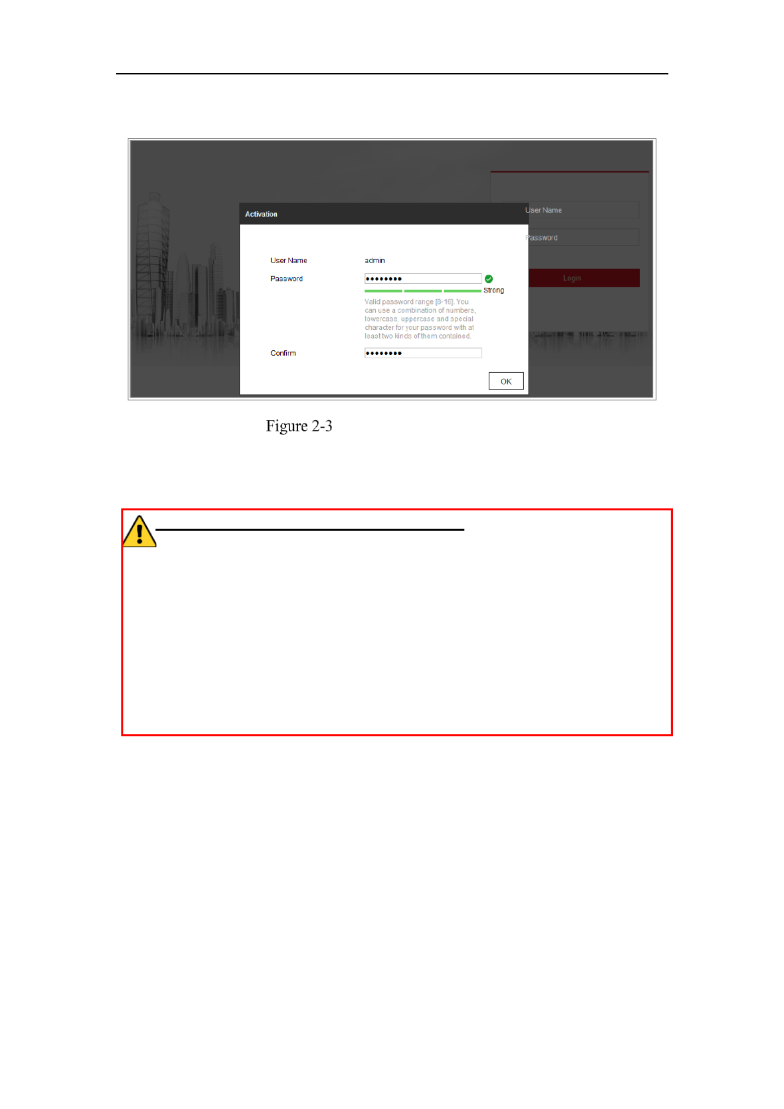
Network Camera User Manual
16
to search the IP address.
Activation via Web Browser
3. Create and input a password into the password field.
A password with user name in it is not allowed.
STRONG PASSWORD RECOMMENDED–We highly recommend you
create a strong password of your own choosing (using a minimum of 8
characters, including at least three of the following categories: upper case letters,
lower case letters, numbers, and special characters) in order to increase the
security of your product. And we recommend you reset your password regularly,
especially in the high security system, resetting the password monthly or weekly
can better protect your product.
4. Confirm the password.
5. Click to save the password and enter the live view interface.OK
Activation via SADP Software
SADP software is used for detecting the online device, activating the camera, and
resetting the password.
Get the SADP software from the supplied disk or the official website, and install the
SADP according to the prompts. Follow the steps to activate the camera.
Steps:
1. Run the SADP software to search the online devices.
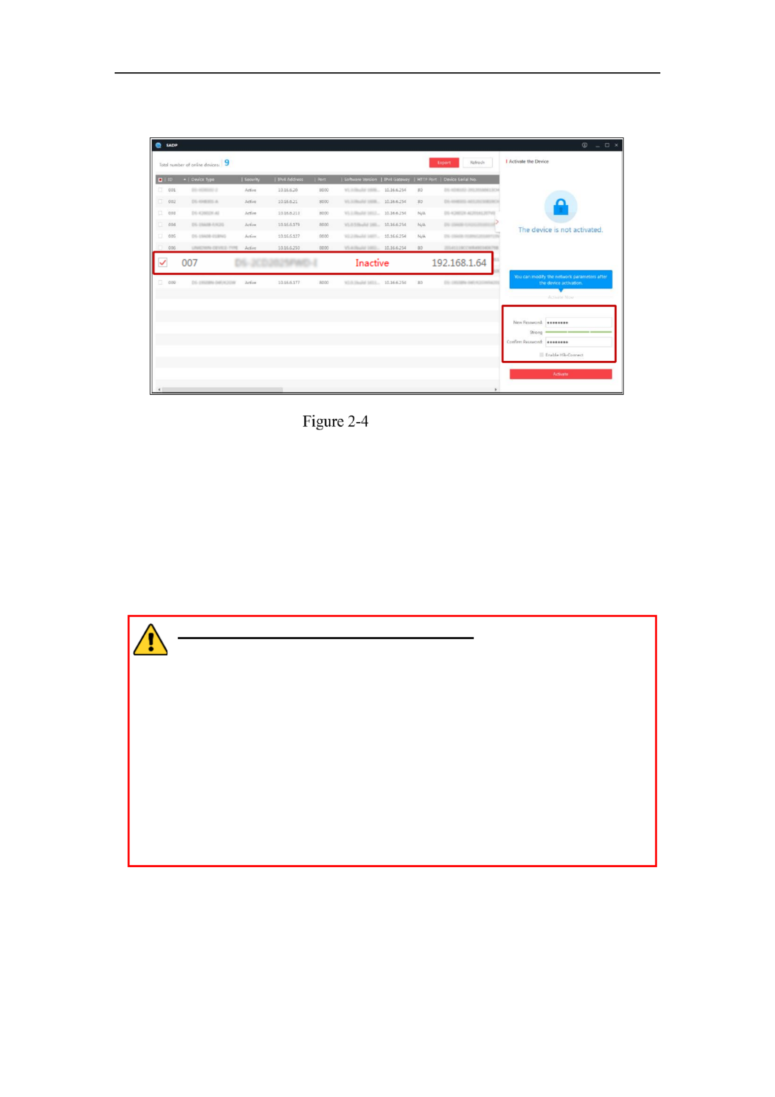
Network Camera User Manual
17
2. Check the device status from the device list, and select the inactive device.
SADP Interface
Note:
The SADP software supports activating the camera in batch. Refer to the user manual
of SADP software for details.
3. Create and input the password in the password field, and confirm the password.
A password with user name in it is not allowed.
STRONG PASSWORD RECOMMENDED– We highly recommend
you create a strong password of your own choosing (using a minimum
of 8 characters, including at least three of the following categories:
upper case letters, lower case letters, numbers, and special characters) in
order to increase the security of your product. And we recommend you
reset your password regularly, especially in the high security system,
resetting the password monthly or weekly can better protect your
product.
Note:
You can enable the Hik Connect service for the device during activation.-
4. Click Activate to start activation.
You can check whether the activation is completed on the popup window. If activation
Select inacve device.
Input and conrm
password.

Network Camera User Manual
18
failed, please make sure that the password meets the requirement and try again.
5. Change the device IP address to the same subnet with your computer by either
modifying the IP address manually or checking the checkbox of Enable DHCP.
Modify the IP Address
6. Input the admin password and click to activate your IP address Modify
modification.
The batch IP address modification is supported by the SADP. Refer to the user manual
of SADP for details.
Activation via Client Software
The client software is versatile video management software for multiple kinds of
devices.
Get the client software from the supplied disk or the official website, and install the
software according to the prompts. Follow the steps to activate the camera.
Steps:
1. Run the client software and the control panel of the software pops up, as shown in

Network Camera User Manual
19
the figure below.
Control Panel
2. Click the icon to enter the Device Management interface, as Device Management
shown in the figure below.

Network Camera User Manual
20
Device Management Interface
3. Check the device status from the device list, and select an inactive device.
4. Click the button to pop up the Activation interface.Activate
5. Create a password and input the password in the password field, and confirm the
password.
A password with user name in it is not allowed.
STRONG PASSWORD RECOMMENDED–We highly recommend
you create a strong password of your own choosing (using a minimum of
8 characters, including at least three of the following categories: upper
case letters, lower case letters, numbers, and special characters) in order
to increase the security of your product. We recommend you reset your
password regularly, especially in the high security system, resetting the
password monthly or weekly can better protect your product.

Network Camera User Manual
22
(Optional) Setting Security Question
Security question is used to reset the admin password when admin user forgets the
password.
Admin user can follow the pop up window to complete security question settings -
during camera activation. Or, admin user can go to interface to set User Management
up the function.
Setting the Network Camera over the WAN
Purpose:
This section explains how to connect the network camera to the WAN with a static IP
or a dynamic IP.
Static IP Connection
Before you start:
Please apply a static IP from an ISP (Internet Service Provider). With the static IP
address, you can connect the network camera via a router or connect it to the WAN
directly.
Connecting the network camera via a router
Steps:
1. Connect the network camera to the router.
2. Assign a LAN IP address, the subnet mask and the gateway. Refer to Section 2.1.2
for detailed IP address configuration of the network camera.
3. Save the static IP in the router.
4. e.g., 80, 8000, and 554 ports. Set port mapping, The steps for port mapping vary
according to the different routers. Please call the router manufacturer for
assistance with port mapping.
Note: Refer to Appendix 2 for detailed information about port mapping.

Network Camera User Manual
23
5. Visit the network camera through a web browser or the client software over the
internet.
Accessing the Camera through Router with Static IP
Connecting the network camera with static IP directly
You can also save the static IP in the camera and directly connect it to the internet
without using a router. Refer to Section 2.1.2 for detailed IP address configuration of
the network camera.
Accessing the Camera with Static IP Directly
Dynamic IP Connection
Before you start:
Please apply a dynamic IP from an ISP. With the dynamic IP address, you can connect
the network camera a modem or a router.to
Connecting the network camera via a router
Steps:
1. Connect the network camera to the router.
2. In the camera, assign a LAN IP address, the subnet mask and the gateway. Refer
to Section 2.1.2 for detailed IP address configuration of the network camera.
3. In the router, set the PPPoE user name, password and confirm the password.
4. E.g. 80, 8000, and 554 ports. Set port mapping. The steps for port mapping vary
depending on different routers. Please call the router manufacturer for assistance

Network Camera User Manual
24
with port mapping.
Note: Refer to Appendix 2 for detailed information about port mapping.
5. Apply a domain name from a domain name provider.
6. Configure the DDNS settings in the setting interface of the router.
7. Visit the camera via the applied domain name.
Connecting the network camera via a modem
Purpose:
This camera supports the PPPoE auto dial up function. The camera gets a public IP -
address by ADSL dial up after the camera is connected to a modem. You need to -
configure the PPPoE parameters of the network camera. Refer to Section 7.1.3
Configuring PPPoE Settings for detailed configuration.
Accessing the Camera with Dynamic IP
Note: The obtained IP address is dynamically assigned via PPPoE, so the IP address
always changes after rebooting the camera. To solve the inconvenience of the
dynamic IP, you need to get a domain name from the DDNS provider (E.g.
DynDns.com). Please follow the steps below for normal domain name resolution and
private domain name resolution to solve the problem.
Normal Domain Name Resolution
Normal Domain Name Resolution
Steps:

Network Camera User Manual
25
1. Apply a domain name from a domain name provider.
2. Configure the DDNS settings in the interface of the network DDNS Settings
camera. Refer to for detailed Section 7.1.2 Configuring DDNS Settings
configuration.
3. Visit the camera via the applied domain name.

Network Camera User Manual
26
Access to the Network
Camera
Accessing by Web Browsers
Note:
For certain camera models, HTTPS is enabled by default and the camera creates an
unsigned certificate automatically. When you access to the camera the first time, the
web browser prompts a notification about the certificate issue.
To cancel the notification, install a signed-certificate to the camera. For detailed
operation, see 7.2.6 HTTPS Settings.
Steps:
1. Open the web browser.
2. In the browser address bar, input the IP address of the network camera, and press
the key to enter the login interface.Enter
Note:
The default IP address is 192.168.1.64. You are recommended to change the IP
address to the same subnet with your computer.
3. Input the user name and password and click . Login
The admin user should configure the device accounts and user/operator permissions
properly. Delete the unnecessary accounts and user/operator permissions.
Note:
The IP address gets locked if the admin user performs 7 failed password attempts
(5 attempts for the user/operator).
Login Interface

Network Camera User Manual
28
iVMS 4200 Control Panel-
iVMS 4200 Main View-

Network Camera User Manual
29
Fi SettingsWi-
Purpose:
By connecting to the wireless network, you don’t need to use cable of any kind for
network connection, which is very convenient for the actual surveillance application.
Note: This chapter is only applicable for the cameras with the built in Wi Fi module.- -
Configuring Wi Fi Connection in Manage and -
Ad- hoc Modes
Purpose:
Two connection modes are supported. Choose a mode as desired and perform the
steps to configure the Wi Fi.-
Wireless Connection in Manage Mode
Steps:
1. Enter the Wi Fi configuration interface.-
Configuration> Network> Advanced Settings> Wi-Fi
2. Click Search to search the online wireless connections.
Wi-Fi List

Network Camera User Manual
30
3. Click to choose a wireless connection on the list.
Wi- - Fi Setting Manage Mode
4. Check the radio button to select the and the Network mode as Manage,
Security mode of the network is automatically shown when you select the
wireless network, please don’t change it manually.
Note: These parameters are exactly identical with those of the router.
5. Enter the key to connect the wireless network. The key should be that of the
wireless network connection you set on the router.
Wireless Connection in Ad hoc Mode-
If you choose the Ad hoc mode, you don’t need to connect the wireless camera via a -
router. The scenario is the same as you connect the camera and the PC directly with a
network cable.
Steps:
1. Choose Ad hoc mode.-
Wi- -Fi Setting Ad- hoc

Network Camera User Manual
31
2. Customize a SSID for the camera.
3. Choose the Security Mode of the wireless connection.
4. Enable the wireless connection function for your PC.
5. On the PC side, search the network and you can see the SSID of the camera
listed.
Ad- hoc Connection Point
6. Choose the SSID and connect.
Security Mode Description:
Security Mode
You can choose the Security Mode as not encrypted, WEP, WPA personal, - -
WPA enterprise, WPA2 personal, and WPA2 enterprise.- - -
WEP mode:

Network Camera User Manual
32
WEP Mode
Authentication Select Open or Shared Key System Authentication, depending on -
the method used by your access point. Not all access points have this option, in
which case they probably use Open System, which is sometimes known as SSID
Authentication.
Key length This sets the length of the key used for the wireless encryption, 64 or -
128 bit. The encryption key length can sometimes be shown as 40/64 and
104/128.
Key type The key types available depend on the access point being used. The -
following options are available:
HEX Allows you to manually enter the hex key.-
ASCII In this method the string must be exactly 5 characters for 64 bit WEP and - -
13 characters for 128 bit WEP.-
WPA personal and WPA2 personal Mode: - -
Enter the required Pre shared Key for the access point, which can be a hexadecimal -
number or a passphrase.
Security Mode WPA personal- -
WPA enterprise and WPA2 enterprise Mode: - -

Network Camera User Manual
34
strongly recommend the use of strong passwords for all functions and network
devices. The password should be something of your own choosing (using a
minimum of 8 characters, including at least three of the following categories:
upper case letters, lower case letters, numbers and special characters) in order to
increase the security of your product.
Proper configuration of all passwords and other security settings is the
responsibility of the installer and/or end user.-
Easy Wi Fi Connection with WPS function-
Purpose:
The setting of the wireless network connection is never easy. To avoid the complex
setting of the wireless connection you can enable the WPS function.
WPS (Wi Fi Protected Setup) refers to the easy configuration of the encrypted -
connection between the device and the wireless router. The WPS makes it easy to add
new devices to an existing network without entering long passphrases. There are two
modes of the WPS connection, the PBC mode and the PIN mode.
Note: If you enable the WPS function, you do not need to configure the parameters
such as the encryption type and you don’t need to know the key of the wireless
connection.
Steps:
Wi- - Fi Settings WPS

Network Camera User Manual
35
PBC Mode:
PBC refers to the Push Button Configuration, in which the user simply has to push a - -
button, either an actual or virtual one (as the button on the configuration
interface of the IE browser), on both the Access Point (and a registrar of the network)
and the new wireless client device.
1. Check the checkbox of to enable WPS.
2. Choose the connection mode as PBC.
Note: Support of this mode is mandatory for both the Access Points and the
connecting devices.
3. Check on the Wi Fi router to see if there is a WPS button. If yes push the button -
and you can see the indicator near the button start flashing, which means the WPS
function of the router is enabled. For detailed operation, please see the user guide of
the router.
4. Push the WPS button to enable the function on the camera.
If there is not a WPS button on the camera, you can also click the virtual button to
enable the PBC function on the web interface.
5. Click button.Connect
When the PBC mode is both enabled in the router and the camera, the camera and the
wireless network is connected automatically.
PIN Mode:
The PIN mode requires a Personal Identification Number (PIN) to be read from either
a sticker or the display on the new wireless device. This PIN must then be entered to
connect the network, usually the Access Point of the network.
Steps:
1. Choose a wireless connection on the list and the SSID is loaded automatically.
2. Choose Use route PIN code.
Network Camera User Manual
36
Use PIN Code
If the PIN code is generated from the router side, you should enter the PIN code you
get from the router side in the Router PIN code field.
3. Click .Connect
Or
You can generate the PIN code on the camera side. And the expired time for the PIN
code is 120 seconds.
1. Click .Generate
2. Enter the code to the router, in the example, enter 48167581 to the router.
IP Property Settings for Wireless Network
Connection
The default IP address of wireless network interface controller is 192.168.1.64. When
you connect the wireless network you can change the default IP.
Steps:
1. Enter the TCP/IP configuration interface.
Configuration> Network> Basic Settings > TCP/IP
2. Select the Wlan tab.
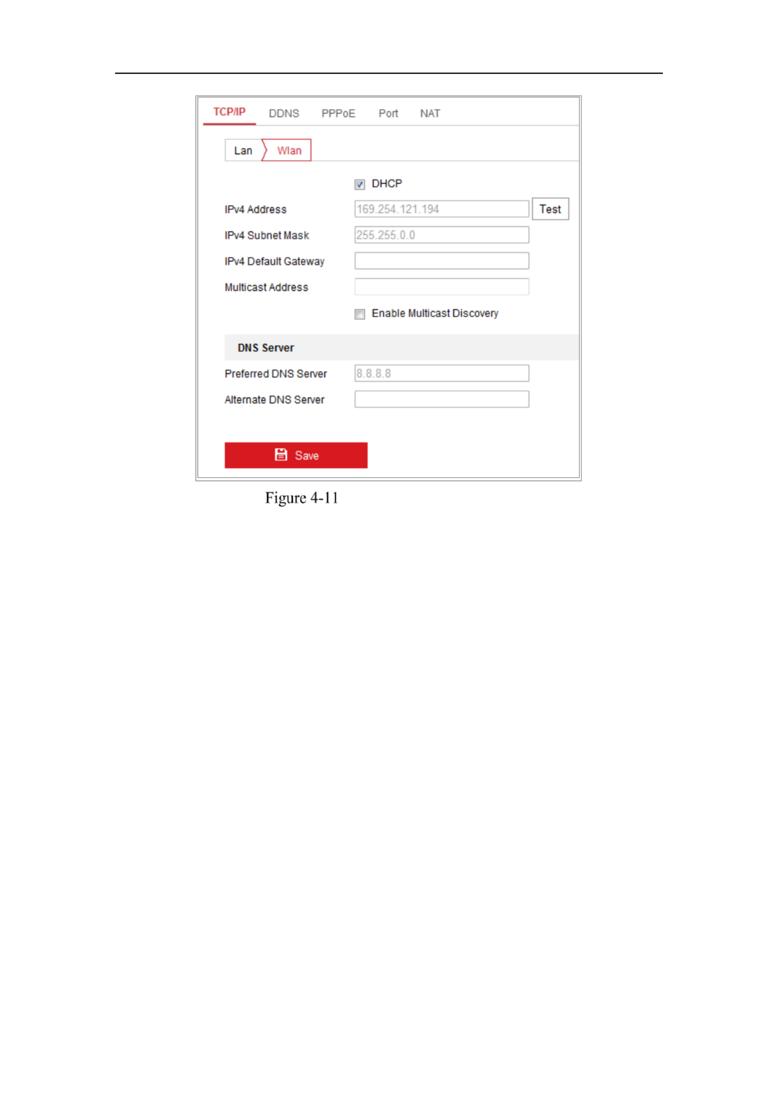
Network Camera User Manual
37
Setting WLAN Parameters
3. Customize the IPv4 address, the IPv4 Subnet Mask and the Default Gateway.
The setting procedure is the same with that of LAN.
If you want to be assigned the IP address you can check the checkbox to enable
the DHCP.

Network Camera User Manual
38
Live View
Live View Page
Purpose:
The live view page allows you to view the real-time video, capture images, realize
PTZ control, set/call presets and configure video parameters.
Log the network camera to enter the live view page, or you can click in Live View on
the menu bar of the main page to enter the live view page.
Descriptions of the live view page:
Toolbar
Live View
Window
Menu Bar
PTZ Control
Panel
Preset/Patrol
Sengs
Live View Page
Menu Bar:
Click each tab to enter Live View, Playback, Picture, Application, and Configuration
page respectively.
Live View Window:
Display the live video.
Toolbar:
Toolbar allows you to adjust the live view window size, the stream type, and the
plug- s. It also allows you to process the o , e.g., in perations on the live view page
start/stop live view, capture, record, audio on/off, two-way audio, start/stop digital
zoom, etc.

Network Camera User Manual
39
For IE (Internet Explorer) users, plug ins webcomponents and quick time are -as
selectable. And for Non IE users, webcomponents, quick time, VLC or MJPEG are -
selectable if they are supported by the web browser.
Note:
For camera that supports plug-in free live view, when Google Chrome 45 and its
above version or Mozilla Firefox 52 and its above version are used, plug-in
installation is not required. But Picture and functions are hidden. To use Playback
mentioned function via web browser, change to their lower versions, or change to
Internet Explorer 8.0 and its above version.
PTZ Control:
Perform panning, tilting and zooming actions of the camera. Control the light and the
wiper (only available for cameras supporting PTZ function).
Preset/Patrol Settings :
Set/call/delete the presets or patrols for PTZ cameras.
Starting Live View
Live Operation
In the live view window as shown in Figure 5 1, click - on the toolbar to start the
live view of the camera.
Live View Toolbar
Toolbar Description
Icon
Description
/
Start/Stop live view.
4:3 window size.
16:9 window size.
Original widow size.
Self-adaptive window size.
Original ratio window size.

Network Camera User Manual
41
Operation
System
Web Browser
Operation
Windows
Internet Explorer 8+
Google Chrome 57 and earlier
version
Mozilla Firefox 52 and earlier
version
Follow pop-up prompts to
complete plug-in installation.
Google Chrome 57+
Mozilla Firefox 52+
Click to download
and install plug-in.
Mac OS
Google Chrome 57+
Mozilla Firefox 52+
Mac Safari 16+
Plug-in installation is not
required.
Enable WebSocket or
WebSockets
(Configuration > Network >
Advanced Settings >
Network Service) for normal
live view.
Display and operation of certain
functions are restricted. For
example, Playback and Picture are
not available. For detailed
restricted function, refer to the
actual device.
Note:
The camera only supports Windows and Mac OS system and do not support Linux
system.
Recording and Capturing Pictures Manually
In the live view interface, click on the toolbar to capture the live pictures or click
to record the live view. The saving paths of the captured pictures and clips can be
set on the page. To configure remote scheduled recording, Configuration > Local
please refer to .Section 6.1
Note: The captured image will be saved as JPEG file or BMP file your computer. in

Network Camera User Manual
42
Live View Quick Setup
It allows quick setup of image/video related parameters on live view page.
Steps:
1. Click button on the right of the live view window to show the PTZ control
panel. Click to hide it.
2. Specify PTZ, Display, OSD and Video/Audio and VCA resource parameters. For
more settings, go to > and > Configuration Image Configuration Video/Audio.
Display Settings
Scene: Select a scene according to actual installation environment. (Only
certain camera models support.)
WDR: The WDR (Wide Dynamic Range) function helps the camera
provide clear images even under back light circumstances. When there
are both very bright and very dark areas simultaneously in the field of
view, WDR balances the brightness level of the whole image and provide
clear images with details. You can enable or disable the WDR function
and set the level.
HLC: High Light Compensation makes the camera identify and suppress
the strong light sources that usually flare across a scene. This makes it
possible to see the detail of the image that would normally be hidden.
OSD (On Screen Display)
Set text information displayed on screen. Alignment adjustment is available
for Text Overlay. Save the settings after configuration.
Video/Audio
Resolution and Max. Bit rate are adjustable. Click to change
stream.
VCA Resource
VCA Resource offers options to enable certain VCA functions and hide
others. It helps allocate more resources to the wanted functions. A reboot is
required after setting the VCA Resource.

Network Camera User Manual
44
For the cameras which support lens movements only, the direction buttons are
invalid.
Descriptions of PTZ Control Panel
Icon
Description
Zoom in/out
Focus near/far
Iris /+-
PTZ speed adjustment
Light on/off
Wiper on/off
Auxiliary focus
Initialize lens
Adjust speed of pan/tilt movements
Start Manual Tracking
Start 3D Zoom
Setting/Calling a Preset
Setting a Preset:
3. In the PTZ control panel, select a preset number from the preset list.
Setting a Preset
4. Use the PTZ control buttons to move the lens the desired position. to
• Pan the camera to the right or left.
• Tilt the camera up or down.

Network Camera User Manual
45
• Zoom in or out.
• Refocus the lens.
5. Click to finish the setting of the current preset.
6. You can click to delete the preset.
Calling a Preset:
This feature enables the camera to point to a specified preset scene manually or when
an event takes place.
For the defined preset, you can call it at any time to the desired preset scene.
In the PTZ control panel, select a defined preset from the list and click to call the
preset.
Or you can place the mouse on the presets interface, and call the preset by typing the
preset No. to call the corresponding presets.
Calling a Preset
Setting/Calling a Patrol
Note:
No less than 2 presets have to be configured before you set a patrol.
Steps:
1. Click to enter the patrol configuration interface.
2. Select a path No., and click to add the configured presets.
3. Select the preset, and input the patrol duration and patrol speed.
4. Click OK to save the first preset.
5. Follow the steps above to add the other presets.

Network Camera User Manual
46
Add Patrol Path
6. Click to save a patrol. OK
7. Click to start the patrol, and click to stop it.
8. (Optional) Click to delete a patrol.

Network Camera User Manual
47
Network Camera
Configuration
Configuring Local Parameters
Purpose:
The local configuration refers to the parameters of the live view, record files and
captured pictures. The record files and captured pictures are the ones you record and
capture using the web browser and thus the saving paths of them are on the PC
running the browser.
Steps:
1. Enter the Local Configuration interface: > . Configuration Local
2. Configure the following settings:
Live View Parameters: Set the protocol type and live view performance.
Protocol Type: TCP, UDP, MULTICAST and HTTP are selectable.
TCP: Ensures complete delivery of streaming data and better video quality,
yet the real time transmission will be affected.-
UDP: Provides real time audio and video streams.-
HTTP: Allows the same quality as of TCP without setting specific ports for
streaming under some network environments.
MULTICAST: It’s recommended to select MCAST type when using the
Multicast function. For detailed information about Multicast, refer to Section
7.1.1 Configuring TCP/IP Settings.
Play Performance: Set the live view performance to Shortest Delay, Balanced,
Fluent or Custom. For Custom, you can set the frame rate for live view.
Rules: It refers to the rules on your local browser, select enable or disable to
display or not display the colored marks when the motion detection, face
detection, or intrusion detection is triggered. E.g., enabled as the rules are, and
the face detection is enabled as well, when a face is detected, it will be marked
with a green rectangle on the live view.

Network Camera User Manual
49
3. Click to save the settings.Save
Configure System Settings
Purpose:
Follow the instructions below to configure the system settings, include System
Settings, Maintenance, Security, and User Management, etc.
Configuring Basic Information
Enter the Device Information interface: Configuration > System > System Settings >
Basic Information.
In the interface, you can edit the Device Name and Device No. Basic Information
Other information of the network camera, such as Model, Serial No., Firmware
Version, Encoding Version, Number of Channels, Number of HDDs, Number of
Alarm Input and Number of Alarm Output are displayed. The information cannot be
changed in this menu. It is the reference for maintenance or modification in future.
Configuring Time Settings
Purpose:
You can follow the instructions in this section to configure the time synchronization
and DST settings.
Steps:
1. Enter the Time Settings interface, Configuration > System> System Settings >
Time Settings.

Network Camera User Manual
51
Note: If the camera is connected to a public network, you should use a NTP server
that has a time synchronization function, such as the server at the National Time
Center (IP Address: 210.72.145.44). If the camera is set in a customized network,
NTP software can be used to establish a NTP server for time synchronization.
Configure the manual time synchronization.
(1) Check the Manual Time Sync. item to enable the manual time
synchronization function.
(2) - Click the icon to select the date, time from the pop up calendar.
(3) (Optional) You can check Sync. with computer time item to synchronize the
time of the device with that of the local PC.
Time Sync Manually
Click to save the settings.Save
Configuring RS232 Settings
The RS232 port can be used in two ways:
Consolo: Connect a computer to the camera through the serial port. Device
parameters can be configured by using software such as HyperTerminal. The
serial port parameters must be the same as the serial port parameters of the
camera.
Transparent Channel: Connect a serial device directly to the camera. The serial
device will be controlled remotely by the computer through the network.
Steps:

Network Camera User Manual
52
1. Enter RS232 Port Setting interface: Configuration System System Settings> > >
RS232.
2. Configure the Baud Rate, Data Bit, Stop Bit, Parity, Flow Control, and Usage.
RS232 Settings
Note: If you want to connect the camera by the RS232 port, the parameters of the
RS232 should be exactly the same with the parameters you configured here.
3. Click to save the settings.Save
Configuring RS485 Settings
Purpose:
The RS485 serial port is used to control the PTZ of the camera. The configuring of
the PTZ parameters should be done before you control the PTZ unit.
Steps:
1. - Enter RS 485 Port Setting interface: Configuration > System > System Settings >
RS485.

Network Camera User Manual
53
RS- 485 Settings
2. Set the RS485 parameters and click to save the settings.Save
By default, the Baud Rate is set as 9600 bps, the Data Bit is 8, the stop bit is 1 and
the Parity and Flow Control is None.
Note: The Baud Rate, PTZ Protocol and PTZ Address parameters should be exactly
the same as the PTZ camera parameters.
Configuring DST Settings
Purpose:
Daylight Saving Time (DST) is a way of making better use of the natural daylight by
setting your clock forward one hour during the summer months, and back again in the
fall.
Configure the DST according to your actual demand.
Steps:
1. Enter the DST configuration interface.
Configuration System System Settings DST> > >

Network Camera User Manual
54
DST Settings
2. Select the start time and the end time.
3. Select the DST Bias.
4. Click to activate the settings.Save
Configuring External Devices
Purpose:
For the device supported external devices, including the wiper on the housing or the
LED light, you can control them via the Web browser. External devices vary
according to the different camera models.
Steps:
1. Enter the External Device configuration interface.
Configuration System System Settings External Device> > >
External Device Settings
2. Check the Enable Supplement Light checkbox to enable the LED Light.
3. Move the slider to adjust the low beam brightness and high bean brightness.
4. Select the mode for LED light. Timing and Auto are selectable.
Timing: The LED will be turned on by the schedule you set. You should set

Network Camera User Manual
55
the Start Time and End Time.
Set Schedule
Auto: The LED will be turned on according to the environment illumination.
5. Click Save to save the settings.
Configuring VCA Resource
Purpose:
VCA resource offers you options to enable certain VCA functions according to actual
need when several VCA functions are available. It helps allocate more resources to
the desired functions.
Steps:
1. Enter VCA Resource configuration interface:
Configuration > System > System Settings > VCA Resource
2. Select a desired VCA combination. Available VCA combination varies according
to different camera models.
3. Click to save the settings. A reboot is required after setting the VCA Save
Resource.
Notes:
• VCA combinations are mutually exclusive. When you activate one combination,
the others are hidden.
• The function may not be supported by some camera models.
Configuring Metadata Settings
Purpose:
Metadata is the raw data the camera collects before algorithm processing. Metadata of
intrusion detection, line crossing detection, region entrance detection, region exiting

Network Camera User Manual
57
upgrade the device.
Enter the Maintenance interface: Configuration > System > Maintenance >
Upgrade & Maintenance.
Reboot: Restart the device.
Restore: Reset all the parameters, except the IP parameters and user information,
to the default settings.
Default: Restore all the parameters to the factory default.
Notes:
• After restoring the default settings, the IP address is also restored to the
default IP address, please be careful for this action.
• For camera that supports Wi Fi, wireless dial, or wlan function, - Restore
action does not restore the related settings of mentioned functions to default.
Information Export
Device Parameters: click to export the current configuration file of the camera.
This operation requires admin password to proceed.
For the exported file, you also have to create an encryption password. The
encryption password is required when you import the file to other cameras.
Diagnose Information: click to download log and system information.
Import Config. File
Configuration file is used for the batch configuration of the camera s.
Steps:
1. Click Browse to select the saved configuration file.
2. Click and input the encryption password that you set during Import
exporting.
Note: You need to reboot the camera after importing configuration file.
Upgrade: Upgrade the device to a certain version.
Steps:
1. Select firmware or firmware directory to locate the upgrade file.
Firmware: Locate the exact path of the upgrade file.
Firmware Directory: Only the directory the upgrade file belongs to is

Network Camera User Manual
58
required.
2. Click Browse Upgradeto select the local upgrade file and then click to start
remote upgrade.
Note: e upgrading process will take 1 to 10 minutes. Please don't disconnect Th
power of the camera during the process, and the camera reboots automatically
after upgrade.
Log
Purpose:
The operation, alarm, exception and information of the camera can be stored in log
files. You can also export the log files on your demand.
Before you start:
Please configure network storage for the camera or insert a SD card in the camera.
Steps:
1. Enter log searching interface: .Configuration > System > Maintenance > Log
Log Searching Interface
2. Set the log search conditions to specify the search, including the Major Type,
Minor Type, Start Time and End Time.
3. Click Search to search log files. The matched log files will be displayed on the
log list interface.
Network Camera User Manual
59
Log Searching
4. To export the log files, click to save the log files.Export
System Service
Purpose:
System service settings refer to the hardware service the camera supports. Supported
functions vary according to the different cameras. For the cameras support IR Light,
ABF (Auto Back Focus), Auto Defog, or Status LED, you can select to enable or
disable the corresponding service according to the actual demands.
ABF: When ABF function is enabled, you can click on PTZ control panel to
realize auxiliary focus.
Third Stream: For some models, third stream is not enabled by default. Check
Enable Third Stream enable the function.to
eMMC Protection If you enable eMMC protection, the lifespan of the eMMC is :
displayed.
Enable Motion Detection: Check to enable the function.Enable Motion Detection
Network Camera User Manual
60
Security Audit Log
Purpose:
The security audit logs refer to the security operation logs. You can search and
analyze the security log files of the camera so that to find out the illegal intrusion and
troubleshooting the security events. Security audit logs can be saved on device flash.
The log will be saved every half hour after device booting.
Due to limited saving space of the flash, you can also save the logs on a log server.
Configure the server settings at Advanced Settings.
Searching Logs
Steps:
1. Enter log searching interface: Configuration > System > Maintenance >
Security Audit Log.
Security Audit Log Searching Interface
2. Set the log search conditions to specify the search, including the Major Type,
Minor Type, Start Time and End Time.
3. Click Search to search log files. The matched log files will be displayed on the
log list interface.

Network Camera User Manual
61
Log Searching
4. To export the log files, click to save the log files.Export
Setting Log Server
Steps:
1. Check Enable Log Upload Server.
2. Input Log Server IP and Log Server Port.
3. Click Test to test settings.
4. Install certificates. Client certificate and CA certificate are required.
• Client Certificate
(1) Click Create button to create the certificate request. Fill in the required
information in the popup window.
(2) Click Download to download the certificate request and submit it to the
trusted certificate authority for signature.
(3) Install the signed certificate to the device.
• CA Certificate
Install the CA certificate to the device.
Security Settings
Configure the parameters, including Authentication, IP Address Filter, and Security
Service from security interface.
Network Camera User Manual
62
Authentication
Purpose:
You can specifically secure the stream data of live view.
Steps:
1. Enter the Authentication interface: Configuration > System > Security >
Authentication.
Authentication
2. Set up authentication method for RTSP authentication and WEB authentication.
Caution:
Digest is the recommended authentication method for better data security. You
must be aware of the risk if you adopt basic as the authentication method.
3. Click to save the settings. Save
IP Address Filter
Purpose:
This function makes it possible for access control.
Steps:
1. Enter the IP Address Filter interface: Configuration > System > Security > IP
Address Filter

Network Camera User Manual
63
IP Address Filter Interface
2. Check the checkbox of Enable IP Address Filter.
3. Select the type of IP Address Filter in the drop down list, and -Forbidden Allowed
are selectable.
4. Set the IP Address Filter list.
Add an IP Address
Steps:
(4) Click the to add an IP.Add
(5) Input the IP Adreess.
Add an IP
(6) Click the to finish adding.OK
Modify an IP Address
Steps:
(1) - Left click an IP address from filter list and click .Modify
(2) Modify the IP address in the text filed.

Network Camera User Manual
64
Modify an IP
(3) Click the to finish modifying.OK
Delete an IP Address or IP Addresses.
Select the IP address(es) and click .Delete
5. Click to save the settings.Save
Security Service
To enable the remote login, and improve the data communication security, the camera
provides the security service for better user experience.
Steps:
1. Enter the security service configuration interface: Configuration > System >
Security Security Service > .
Security Service
2. Check the checkbox of .Enable Illegal Login Lock
Illegal Login Lock: it is used to limit the user login attempts. Login attempt from
the IP address is rejected if admin user performs 7 failed user name/password
attempts (5 times for the operator/user).
Note: If the IP address is rejected, you can try to login the device after 30 minutes.
Advanced Security
Purpose:

Network Camera User Manual
65
Advanced security offers options to manage more network security settings of the
device.
Security Reinforce
Check the checkbox to enable the function. Security reinforce is a solution to
enhance network security. With the function enabled, risky functions, protocols,
ports of the device are disabled and more secured alternative functions, protocols
and ports are enabled.
Control Timeout Settings
If you enable the function and set timeout period, you will be logged out when
you make no operation to the device via web browser (Viewing live image and
playback are not included.) for the set timeout period.
Algorithm
Displays the currently active digest algorithm. If Security Reinforce is enabled,
MD5 is disabled and SHA256 is enabled instead.
User Management
User Management
As Administrator
The admin user can add, delete or modify user accounts, and grant them different
permissions. We highly recommend you manage the user accounts and
permissions properly.
Enter the User Management interface: > > Configuration System User
Management
Note:
Admin password if required for adding and modifying a user account.

Network Camera User Manual
66
User Management Interface
Adding a User
The user has all permissions by default and can create/modify/delete other admin
accounts.
The user cannot be deleted and you can only change the password.admin admin
Steps:
1. Click to add a user.Add
2. Input the Admin Password User Name Level Password., , select and input
Notes:
● Up to 31 user accounts can be created.
● Users of different levels own different default permissions. Operator and
user are selectable.
STRONG PASSWORD RECOMMENDED–We highly recommend you
create a strong password of your own choosing (using a minimum of 8
characters, including at least three of the following categories: upper case
letters, lower case letters, numbers, and special characters) in order to
increase the security of your product. And we recommend you reset your
password regularly, especially in the high security system, resetting the
password monthly or weekly can better protect your product.
3. You can check or uncheck the permissions for the new user.
4. Click to finish the user addition.OK
Modifying a User
Steps:
1. - Left click to select the user from the list and click . Modify

Network Camera User Manual
68
available.
Set Account Security:
You can set the security questions during camera activation. Or you can set the
function at user management interface.
Security question setting is not cleared when you restore the camera (not to default).
Steps:
1. Enter setting interface:
Configuration > System > User Management > User Management
2. Click Account Security Settings.
3. Select questions and input answers.
4. - Enter the E mail address to receive the verification code for password recovery.
5. Click to save the settings. OK
Reset Admin Password:
Before you start:
The PC used to reset password and the camera should belong to the same IP address
segment of the same LAN.
Steps:
1. Enter login interface via web browser.
2. Click .Forget Password
3. Select the verification mode to E mail Verification-.
4. Read the Privacy Policy and click .OK
5. Click and save the code to local.Export QR Code
6. Send the code to pw_recovery@hikvision.com as an attachment. Your email
account for password recovery will receive a verification code in 5 minutes.
Note:
The verification code is valid within 48 hours.
7. Input the verification code in the text field below.

Network Camera User Manual
71
Network Settings
Purpose:
Follow the instructions in this chapter to configure the basic settings and advanced
settings.
Configuring Basic Settings
Purpose:
You can configure the parameters, including TCP/IP, DDNS, PPPoE, Port, and NAT,
etc., by following the instructions in this section.
Configuring TCP/IP Settings
Purpose:
TCP/IP settings must be properly configured before you operate the camera over
network. The camera supports both the IPv4 and IPv6. Both versions can be
configured simultaneously without conflicting to each other, and at least one IP
version should be configured.
Steps:
1. Enter TCP/IP Settings interface: Configuration > Network > Basic
Settings > TCP/IP

Network Camera User Manual
72
TCP/IP Settings
2. NIC Type, IPv4 or IPv6 Configure the basic network settings, including the
Address, IPv4 or IPv6 Subnet Mask, IPv4 or IPv6 Default Gateway, MTU settings
and Multicast Address.
3. (Optional) Check the checkbox of , and then the Enable Multicast Discovery
online network camera can be automatically detected by client software via
private multicast protocol in the LAN.
4. Configure the DNS server. Input the preferred DNS server, and alternate DNS
server.
5. Click to save the above settings Save .
Notes:
The valid value range of MTU is 1280 1500. to
The Multicast sends a stream to the multicast group address and allows multiple
clients to acquire the stream at the same time by requesting a copy from the

Network Camera User Manual
75
Configuring PPPoE Settings
Steps:
1. Enter the PPPoE Settings interface: Configuration > Network > Basic Settings >
PPPoE
PPPoE Settings
2. Check the checkbox to enable this feature. Enable PPPoE
3. Enter , , and password for PPPoE access. User Name Password Confirm
Note: The User Name and Password should be assigned by your ISP.
For your privacy and to better protect your system against security risks, we
strongly recommend the use of strong passwords for all functions and network
devices. The password should be something of your own choosing (using a
minimum of 8 characters, including at least three of the following categories:
upper case letters, lower case letters, numbers and special characters) in order to
increase the security of your product.
Proper configuration of all passwords and other security settings is the
responsibility of the installer and/or end user.-
4. Click to save and exit the interface. Save
Note: A reboot is required for the settings to take effect.
Configuring Port Settings
Purpose:

Network Camera User Manual
80
minimum of 8 characters, including at least three of the following categories:
upper case letters, lower case letters, numbers and special characters) in order to
increase the security of your product.
Proper configuration of all passwords and other security settings is the
responsibility of the installer and/or end user.-
Steps:
1. Enter the SNMP Settings interface: Configuration > Network > Advanced
Settings > SNMP.

Network Camera User Manual
81
SNMP Settings
2. Check the checkbox of Enable SNMPv1, Enable SNMP v2c, Enable SNMPv3 to
enable the feature correspondingly.
3. Configure the SNMP settings.
Note: The settings of the SNMP software should be the same as the settings you

Network Camera User Manual
83
3. Input the server address and port.
4. Configure the FTP/SFTP settings; and the user name and password are required
for the server login.
For your privacy and to better protect your system against security risks, we
strongly recommend the use of strong passwords for all functions and
network devices. The password should be something of your own choosing
(using a minimum of 8 characters, including at least three of the following
categories: upper case letters, lower case letters, numbers and special
characters) in order to increase the security of your product.
Proper configuration of all passwords and other security settings is the
responsibility of the installer and/or end user.-
5. Set the directory structure and picture filing interval.
Directory Directory Structure: In the field, you can select the root directory,
parent directory and child directory. When the parent directory is selected, you
have the option to use the Device Name, Device Number or Device IP for the
name of the directory; and when the Child Directory is selected, you can use the
Camera Name or Camera No. as the name of the directory.
Picture Filing Interval: For better picture management, you can set the picture
filing interval from 1 day to 30 days. Pictures captured in the same time interval
will be saved in one folder named after the beginning date and ending date of the
time interval.
Picture Name: Set the naming rule for captured picture files. You choose can
Default in the drop down list to use the default rule, that is, -
IP address_channel number_capture time_event type.jpg
(e.g., 10.11.37.189_01_20150917094425492_FACE_DETECTION.jpg).
Or you can customize it by adding a Custom Prefix to the default naming rule.
6. Check the Upload Picture checkbox to enable the function.
Upload Picture: To enable uploading the captured picture to the FTP server.

Network Camera User Manual
88
3. Configure the dial parameters.
1) - Select the dial mode from the drop down list. Auto and Manual are selectable.
If Auto is selected, you can set the arming schedule for dialing; If Manual is
selected, you can set the offline time and manual dialing parameters.
2) Set the access number, user name, password, APN, MTU and verification
protocol. You can also leave these parameters blank, and the device will
adopt the default settings for dialing after other parameters are configured.
3) - Select the network mode from the drop down list. Auto, 3G and 4G are
selectable. If Auto is selected, the network selection priority comes as: 4G >
3G > Wired Network.
4) Input the offline time if Manual is selected as the dial mode.
5) Input the UIM Number (Mobile Phone Number).
6) Click the Edit button to set the arming schedule if Auto is selected as the dial
mode.
7) Click Save to save the settings.
4. View the dial status.
1) - Click the Refresh button to view the dial status including real time mode,
UIM status, signal strength, etc.
2) If Manual is selected as the dial mode, you can also manually connect /
disconnect the wireless network.
5. Set the white list. The mobile phone number on the white list can receive the
alarm message from the device and reboot the device via SMS.
1) Check the checkbox of Enable SMS Alarm.
2) Select the item on the white list, and click the Edit button.
3) Input the mobile phone number for the white list, check the checkbox of
Reboot via SMS, select the alarm for SMS push, and click OK.
Note: To reboot the device via SMS, send the message "reboot" to the device,
and the device will reply a message "reboot success" after rebooting
succeeded.
4) (Optional) You can click Send Test SMS to send a message to the mobile
Specyfikacje produktu
| Marka: | Hikvision |
| Kategoria: | Kamera monitorująca |
| Model: | DS-2CD2425FWD-IW |
Potrzebujesz pomocy?
Jeśli potrzebujesz pomocy z Hikvision DS-2CD2425FWD-IW, zadaj pytanie poniżej, a inni użytkownicy Ci odpowiedzą
Instrukcje Kamera monitorująca Hikvision

12 Stycznia 2025
12 Stycznia 2025
12 Stycznia 2025
12 Stycznia 2025
11 Stycznia 2025
7 Stycznia 2025
19 Grudnia 2024
19 Grudnia 2024
19 Grudnia 2024
19 Grudnia 2024
Instrukcje Kamera monitorująca
- Kamera monitorująca Sony
- Kamera monitorująca Samsung
- Kamera monitorująca Tenda
- Kamera monitorująca Motorola
- Kamera monitorująca Stabo
- Kamera monitorująca Logitech
- Kamera monitorująca Xiaomi
- Kamera monitorująca Braun
- Kamera monitorująca Pioneer
- Kamera monitorująca TP-Link
- Kamera monitorująca Philips
- Kamera monitorująca Bosch
- Kamera monitorująca Gigaset
- Kamera monitorująca EZVIZ
- Kamera monitorująca Conceptronic
- Kamera monitorująca Panasonic
- Kamera monitorująca Canon
- Kamera monitorująca Crestron
- Kamera monitorująca Withings
- Kamera monitorująca Asus
- Kamera monitorująca Nedis
- Kamera monitorująca AG Neovo
- Kamera monitorująca Reolink
- Kamera monitorująca Boss
- Kamera monitorująca TRENDnet
- Kamera monitorująca Marquant
- Kamera monitorująca Toshiba
- Kamera monitorująca D-Link
- Kamera monitorująca August
- Kamera monitorująca Niceboy
- Kamera monitorująca Ring
- Kamera monitorująca Garmin
- Kamera monitorująca Imou
- Kamera monitorująca Blaupunkt
- Kamera monitorująca Grundig
- Kamera monitorująca APC
- Kamera monitorująca Honeywell
- Kamera monitorująca BLOW
- Kamera monitorująca Manhattan
- Kamera monitorująca Strong
- Kamera monitorująca Swann
- Kamera monitorująca Kwikset
- Kamera monitorująca Kodak
- Kamera monitorująca Cisco
- Kamera monitorująca ORNO
- Kamera monitorująca Broan
- Kamera monitorująca Moxa
- Kamera monitorująca Synology
- Kamera monitorująca Gembird
- Kamera monitorująca ZTE
- Kamera monitorująca Turing
- Kamera monitorująca Lindy
- Kamera monitorująca Minox
- Kamera monitorująca Zebra
- Kamera monitorująca DSC
- Kamera monitorująca JVC
- Kamera monitorująca ZyXEL
- Kamera monitorująca Trust
- Kamera monitorująca LogiLink
- Kamera monitorująca Furrion
- Kamera monitorująca Linksys
- Kamera monitorująca Google
- Kamera monitorująca Digitus
- Kamera monitorująca Vimar
- Kamera monitorująca V-TAC
- Kamera monitorująca Dahua Technology
- Kamera monitorująca Schneider
- Kamera monitorująca Eufy
- Kamera monitorująca Ricoh
- Kamera monitorująca Emos
- Kamera monitorująca AVMATRIX
- Kamera monitorująca Renkforce
- Kamera monitorująca Rollei
- Kamera monitorująca Marshall
- Kamera monitorująca Perel
- Kamera monitorująca Somfy
- Kamera monitorująca Uniden
- Kamera monitorująca Netgear
- Kamera monitorująca Thomson
- Kamera monitorująca DiO
- Kamera monitorująca Velleman
- Kamera monitorująca Ferguson
- Kamera monitorująca DataVideo
- Kamera monitorująca Delta Dore
- Kamera monitorująca Pyle
- Kamera monitorująca Intellinet
- Kamera monitorująca CRUX
- Kamera monitorująca Setti+
- Kamera monitorująca Waeco
- Kamera monitorująca Vivotek
- Kamera monitorująca Vtech
- Kamera monitorująca Speco Technologies
- Kamera monitorująca EtiamPro
- Kamera monitorująca Edimax
- Kamera monitorująca Petcube
- Kamera monitorująca ION
- Kamera monitorująca First Alert
- Kamera monitorująca AirLive
- Kamera monitorująca Maginon
- Kamera monitorująca EnGenius
- Kamera monitorująca SPC
- Kamera monitorująca Planet
- Kamera monitorująca Brilliant
- Kamera monitorująca Genie
- Kamera monitorująca LevelOne
- Kamera monitorująca Axis
- Kamera monitorująca Sanyo
- Kamera monitorująca Lorex
- Kamera monitorująca Control4
- Kamera monitorująca Milesight
- Kamera monitorująca Aluratek
- Kamera monitorująca Abus
- Kamera monitorująca Elro
- Kamera monitorująca Olympia
- Kamera monitorująca Hama
- Kamera monitorująca Marmitek
- Kamera monitorująca Ubiquiti Networks
- Kamera monitorująca Western Digital
- Kamera monitorująca Netatmo
- Kamera monitorująca Schwaiger
- Kamera monitorująca Promise Technology
- Kamera monitorująca GVI Security
- Kamera monitorująca AVer
- Kamera monitorująca ZKTeco
- Kamera monitorująca Netis
- Kamera monitorująca Extech
- Kamera monitorująca Denver
- Kamera monitorująca Anker
- Kamera monitorująca Allnet
- Kamera monitorująca Marshall Electronics
- Kamera monitorująca Orion
- Kamera monitorująca Yale
- Kamera monitorująca SereneLife
- Kamera monitorująca Ernitec
- Kamera monitorująca AVerMedia
- Kamera monitorująca MEE Audio
- Kamera monitorująca Genius
- Kamera monitorująca Trevi
- Kamera monitorująca Technaxx
- Kamera monitorująca Atlona
- Kamera monitorująca Hanwha
- Kamera monitorująca Overmax
- Kamera monitorująca Quantum
- Kamera monitorująca Y-cam
- Kamera monitorująca Grandstream
- Kamera monitorująca Raymarine
- Kamera monitorująca Powerfix
- Kamera monitorująca Avanti
- Kamera monitorująca Ikan
- Kamera monitorująca Alecto
- Kamera monitorująca Avidsen
- Kamera monitorująca JUNG
- Kamera monitorująca Burg Wächter
- Kamera monitorująca Foscam
- Kamera monitorująca Lumens
- Kamera monitorująca Monacor
- Kamera monitorująca Dörr
- Kamera monitorująca M-e
- Kamera monitorująca EVE
- Kamera monitorująca Smartwares
- Kamera monitorująca Adj
- Kamera monitorująca Qian
- Kamera monitorująca Arenti
- Kamera monitorująca Elmo
- Kamera monitorująca Vitek
- Kamera monitorująca Alfatron
- Kamera monitorująca UniView
- Kamera monitorująca Clas Ohlson
- Kamera monitorująca Laserliner
- Kamera monitorująca Megasat
- Kamera monitorująca REVO
- Kamera monitorująca BZBGear
- Kamera monitorująca BirdDog
- Kamera monitorująca KJB Security Products
- Kamera monitorująca HiLook
- Kamera monitorująca Profile
- Kamera monitorująca Aldi
- Kamera monitorująca Aritech
- Kamera monitorująca Acti
- Kamera monitorująca ACME
- Kamera monitorująca Flamingo
- Kamera monitorująca Caliber
- Kamera monitorująca Eminent
- Kamera monitorująca Sitecom
- Kamera monitorująca Exibel
- Kamera monitorująca Fortinet
- Kamera monitorująca KlikaanKlikuit
- Kamera monitorująca Trebs
- Kamera monitorująca Ednet
- Kamera monitorująca Steren
- Kamera monitorująca Flir
- Kamera monitorująca Buffalo
- Kamera monitorująca Arlo
- Kamera monitorująca Nest
- Kamera monitorująca Siedle
- Kamera monitorująca Hive
- Kamera monitorująca Switel
- Kamera monitorująca Chacon
- Kamera monitorująca InFocus
- Kamera monitorująca Hombli
- Kamera monitorująca Naxa
- Kamera monitorująca Konig
- Kamera monitorująca Valueline
- Kamera monitorująca BRK
- Kamera monitorująca QSC
- Kamera monitorująca Xavax
- Kamera monitorująca Vaddio
- Kamera monitorująca Gira
- Kamera monitorująca Interlogix
- Kamera monitorująca Boyo
- Kamera monitorująca IC Intracom
- Kamera monitorująca Iget
- Kamera monitorująca EverFocus
- Kamera monitorująca Adesso
- Kamera monitorująca Satel
- Kamera monitorująca POSline
- Kamera monitorująca Notifier
- Kamera monitorująca Hawking Technologies
- Kamera monitorująca Friedland
- Kamera monitorująca Nexxt
- Kamera monitorująca Monoprice
- Kamera monitorująca Watec
- Kamera monitorująca Beafon
- Kamera monitorująca Chuango
- Kamera monitorująca ETiger
- Kamera monitorująca Videcon
- Kamera monitorująca INSTAR
- Kamera monitorująca Provision ISR
- Kamera monitorująca Aqara
- Kamera monitorująca Advantech
- Kamera monitorująca Digital Watchdog
- Kamera monitorująca Ganz
- Kamera monitorująca AViPAS
- Kamera monitorująca ClearOne
- Kamera monitorująca Ebode
- Kamera monitorująca Oplink
- Kamera monitorująca Sonic Alert
- Kamera monitorująca Linear PRO Access
- Kamera monitorująca Summer Infant
- Kamera monitorująca SMC
- Kamera monitorująca Topica
- Kamera monitorująca Kogan
- Kamera monitorująca Iiquu
- Kamera monitorująca Verint
- Kamera monitorująca Brinno
- Kamera monitorująca Rostra
- Kamera monitorująca Caddx
- Kamera monitorująca Spyclops
- Kamera monitorująca EKO
- Kamera monitorująca Kguard
- Kamera monitorująca Woonveilig
- Kamera monitorująca Mobi
- Kamera monitorująca Surveon
- Kamera monitorująca Hollyland
- Kamera monitorująca Epcom
- Kamera monitorująca Indexa
- Kamera monitorująca Lutec
- Kamera monitorująca Whistler
- Kamera monitorująca ClearView
- Kamera monitorująca VideoComm
- Kamera monitorująca IMILAB
- Kamera monitorująca 3xLOGIC
- Kamera monitorująca Pelco
- Kamera monitorująca Leviton
- Kamera monitorująca Inkovideo
- Kamera monitorująca Pentatech
- Kamera monitorująca Weldex
- Kamera monitorująca SecurityMan
- Kamera monitorująca Canyon
- Kamera monitorująca CNB Technology
- Kamera monitorująca Tapo
- Kamera monitorująca Aigis
- Kamera monitorująca Exacq
- Kamera monitorująca Brickcom
- Kamera monitorująca Laxihub
- Kamera monitorująca Securetech
- Kamera monitorująca EFB Elektronik
- Kamera monitorująca NetMedia
- Kamera monitorująca Videotec
- Kamera monitorująca Illustra
- Kamera monitorująca Nivian
- Kamera monitorująca E-bench
- Kamera monitorująca Syscom
- Kamera monitorująca Tecno
- Kamera monitorująca Night Owl
- Kamera monitorująca Guardzilla
- Kamera monitorująca Astak
- Kamera monitorująca Blink
- Kamera monitorująca Milestone Systems
- Kamera monitorująca Zavio
- Kamera monitorująca Campark
- Kamera monitorująca IPX
- Kamera monitorująca Dedicated Micros
- Kamera monitorująca Hamlet
- Kamera monitorująca Annke
- Kamera monitorująca AVTech
- Kamera monitorująca Qoltec
- Kamera monitorująca Approx
- Kamera monitorująca Digimerge
- Kamera monitorująca Wisenet
- Kamera monitorująca Infortrend
- Kamera monitorująca Epiphan
- Kamera monitorująca Mach Power
- Kamera monitorująca Compro
- Kamera monitorująca Aida
- Kamera monitorująca Ikegami
- Kamera monitorująca Accsoon
- Kamera monitorująca Vimtag
- Kamera monitorująca Gewiss
- Kamera monitorująca Alula
- Kamera monitorująca Insteon
- Kamera monitorująca Costar
- Kamera monitorująca ALC
- Kamera monitorująca Security Labs
- Kamera monitorująca Comtrend
- Kamera monitorująca Seneca
- Kamera monitorująca Avigilon
- Kamera monitorująca American Dynamics
- Kamera monitorująca Vosker
- Kamera monitorująca Sentry360
- Kamera monitorująca Bea-fon
- Kamera monitorująca Owltron
- Kamera monitorująca Enabot
- Kamera monitorująca Luis Energy
- Kamera monitorująca Sir Gawain
- Kamera monitorująca VisorTech
- Kamera monitorująca Atlantis Land
- Kamera monitorująca B & S Technology
- Kamera monitorująca I3International
- Kamera monitorująca IDIS
- Kamera monitorująca Ecobee
- Kamera monitorująca Conbrov
- Kamera monitorująca HuddleCamHD
- Kamera monitorująca Mobotix
- Kamera monitorująca IOIO
- Kamera monitorująca BIRDFY
- Kamera monitorująca I-PRO
- Kamera monitorująca DVDO
- Kamera monitorująca TCP
- Kamera monitorująca Bolin Technology
- Kamera monitorująca Nextech
Najnowsze instrukcje dla Kamera monitorująca

28 Stycznia 2025
25 Stycznia 2025
17 Stycznia 2025
15 Stycznia 2025

13 Stycznia 2025

13 Stycznia 2025
13 Stycznia 2025
12 Stycznia 2025
12 Stycznia 2025
12 Stycznia 2025