Instrukcja obsล‚ugi Gewiss GW90759

Przeczytaj poniลผej ๐Ÿ“– instrukcjฤ™ obsล‚ugi w jฤ™zyku polskim dla Gewiss GW90759 (2 stron) w kategorii Niesklasyfikowane. Ta instrukcja byล‚a pomocna dla 2 osรณb i zostaล‚a oceniona przez 2 uลผytkownikรณw na ล›rednio 4.5 gwiazdek

Strona 1/2
Cod. 7.01.0.350.2
๎€—%๎€Ÿ*๎€š ๎€Ÿ๎€–
Lโ€™attuatore dimmer 2x300 W (art. GW 90 759) puรฒ regolare lampade ad
incandescenza e carichi induttivi (lampade alogene con trasformatori ad
avvolgimento dimmerabili) con una potenza massima di 300 Watt/VA per
ogni canale ( ).-87=;8558๎€€.3๎€€0+</
๎€ž ๎€Ÿ$๎€’๎€˜๎€˜๎€š
!๎€–"๎€š๎€” ๎€ ๎€€๎€•๎€š๎€€๎€ž "$๎€–๎€๎€€
Tutte le operazioni sullโ€™apparecchiatura devono essere eseguite da
personale elettricista qualificato. Fare attenzione alle disposizioni
nazionali specifiche nonchรฉ alle direttive EIB in vigore.
!๎€–"๎€š๎€” ๎€ ๎€€๎€•๎€š๎€€๎€ž "$๎€–๎€๎€€
Le uscite possono essere sotto tensione anche con il dimmer spento.
Durante i lavori sulle utenze collegate, togliere sempre la tensione
tramite lโ€™interruttore automatico a monte.
๎€’$$๎€–๎€Ÿ*๎€š ๎€Ÿ๎€–๎€€
Tutti gli apparecchi che sono montati a fianco dellโ€™attuatore dimmer,
devono essere provvisti almeno di un isolamento base!
๎€’$$๎€–๎€Ÿ*๎€š ๎€Ÿ๎€–๎€€
Durante il funzionamento, il dimmer necessita di un carico minimo di
25 W/VA. In caso di carico inferiore possono verificarsi dei
malfunzionamenti.
Lโ€™attuatore dimmer GW 90 759 รจ unโ€™apparecchiatura modulare e viene
montata su una guida ad istallazione rapida DIN-EN 50022. Un binario dati
non รจ necessario.
Il collegamento bus avviene tramite il morsetto di collegamento bus incluso
nella fornitura. Successivamente viene inserito il copricavo sul morsetto di
collegamento bus al fine di garantire la dovuta distanza di sicurezza tra la
linea bus e la linea di alimentazione da 230V.
Al morsetto di collegamento bus possono essere connesse al massimo 4
coppie di fili. La linea verso lโ€™utenza e la rete di alimentazione sono collegate
tramite morsetti ad innesto con viti.
I cavi possono essere prima avvitati sulla morsettiera dellโ€™apparecchiatura e
innestati successivamente. Lโ€™innesto del morsetto deve avvenire in assenza
di tensione. Il led verde di servizio "RUN" si accende solamente quando il
programma applicativo รจ stato caricato correttamente nellโ€™apparecchio.
Il led verde di servizio "RUN" indica tramite una regolare intermittenza (circa
1 volta per secondo) un eventuale sovraccarico.
In presenza di sovraccarico, il relativo canale dimmer viene spento in modo
permanente.
Il ripristino del canale dimmer puรฒ avvenire come segue:
- mediante la ricezione di un telegramma off
- mediante temporaneo scollegamento della tensione di rete
- mediante un reset del bus (circa 20 secondi)
Un corto circuito in uscita ha effetto su entrambi i canali, la protezione รจ
assicurata tramite un fusibile integrato (T2,5H). Lโ€™apparecchio รจ dotato di 4
morsetti ad innesto con viti:
- 1 morsetto per il conduttore di Neutro
- 1 morsetto per il conduttore di fase
- 2 morsetti per le linee di carichi dimmerabili
Non deve essere superata la temperatura ambiente prescritta.
๎€•๎€’$๎€š๎€€$๎€–๎€”๎€Ÿ๎€š๎€”๎€š
๎€’536/7=+C387/๎€€.+5๎€€,><๎€ DC 24V / ca. 10 mA
$/7<387/๎€€.3๎€€3<85+6/7=8๎€ AC 4 kV bus/tensione di rete
$/7<387/๎€€78637+5/๎€ AC 230 V / 50 Hz
!8=/7C+๎€€78637+5/๎€€๎€9/;๎€€8173๎€€-+7+5/๎€‚
- Lampade incandescenti: 25-300 W
- Lampade alogene HV: 25-300 W (HV=alta tensione)
- Carichi induttivi: 25-300 VA
๎€”+;3-8๎€€637368๎€€๎€9/;๎€€8173๎€€-+7+5/๎€‚๎€ 25 W/VA
!;8=/C387/๎€€-87=;8
- cortocircuito: fusibile (T2.5H)
- sovraccarico: (per ogni canale) protezione elettronica
$/69/;+=>;+๎€€+6,3/7=/
- funzionamento: da -5 ยฐC fino a +45 ยฐC
- stoccaggio: da -25 ยฐC fino a +55 ยฐC
- trasporto: da -25 ยฐC fino a +70 ยฐC
%63.3=D๎€€6+<<36+๎€ 93 % di umiditร  relativa, nessuna formazione di condensa
๎€’6,3/7=/๎€Lโ€™apparecchio รจ realizzato per lโ€™impiego ad unโ€™altezza massima di
2000 m sul livello del mare (MSL).
๎€–5/6/7=8๎€€.3๎€€-86+7.8๎€ pulsante di programmazione
๎€–5/6/7=8๎€€.3๎€€ </17+5+C387/๎€ led rosso per il controllo della tensione bus e
inserimento dellโ€™indirizzo fisico
led verde per segnalazione applicazione in corso e intermittente per la
segnalazione di sovraccarico
๎€”855/1+6/7=3
- Bus: tramite due pin da 1 mm per il morsetto di collegamento bus
- Conduttore neutro: morsetti ad innesto con viti per massimo 2,5 mm
2
- Conduttore di fase: morsetti ad innesto con viti per massimo 2,5 mm
2
- Linee dei carichi dimmerabili: morsetti ad innesto con viti per
massimo 2,5 mm2
$398๎€€.3๎€€9;8=/C387/๎€ IP20
๎€•3;/==3?/๎€€%๎€–๎€ Corrisponde alla direttiva sulla la bassa tensione 73/23/CEE;
corrisponde alla direttiva sulla compatibilitร  elettromagnetica 89/336/CEE
๎€•36/7<3873๎€ 90x108x65 mm (AxLxP)
๎€+;12/CC+๎€€+99+;/--238๎€ 6 moduli EN 50022 = 108 mm
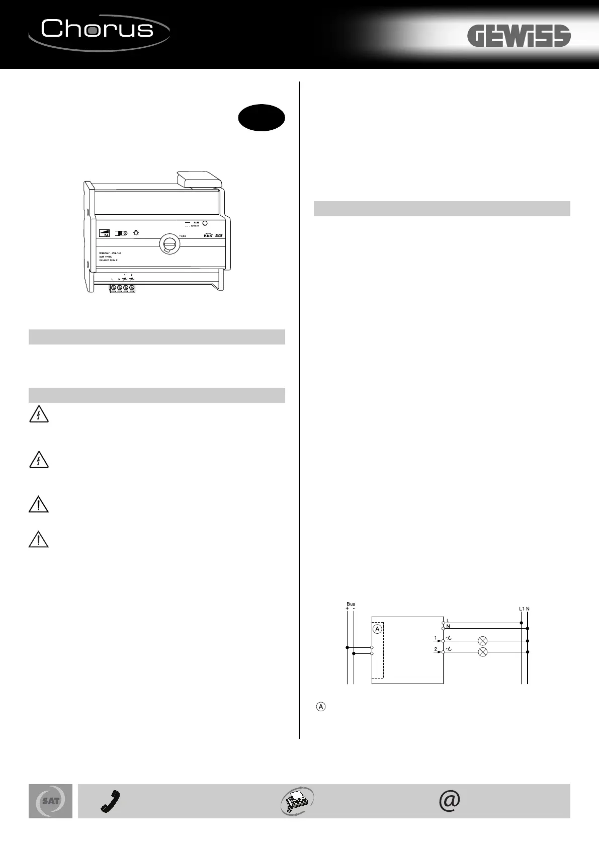
Esempio di collegamento:
unitร  di accoppiamento bus
๎€’$$%๎€’$ "๎€–๎€€๎€•๎€š๎€ž๎€ž๎€–"๎€€"๎€–#๎€š#$๎€š& ๎€…๎€š๎€Ÿ๎€•%$$๎€š&
๎€‰(๎€Š๎€‡๎€‡'
Articolo n.
๎€˜'๎€€๎€๎€‡๎€€๎€Ž๎€Œ๎€ Colore
grigio chiaro
I
+39 035 946 111
8.30 - 12.30 / 14.00 - 18.00
lunedรฌ รท venerdรฌ - monday รท friday
+39 035 946 260 sat@gewiss.com
www.gewiss.com
24h
Ai sensi dellโ€™articolo 9 comma 2 della Direttiva Europea 2004/108/CE e dellโ€™articolo R2 comma 6 della Decisione 768/2008/CE si informa che responsabile dellโ€™immissione del prodotto sul mercato Comunitario รจ:
According to article 9 paragraph 2 of the European Directive 2004/108/EC and to article R2 paragraph 6 of the Decision 768/2008/EC, the responsible for placing the apparatus on the Community market is:
๎€˜๎€–'๎€š##๎€€#๎€†9๎€†๎€’๎€€๎€€&3+๎€€๎€’๎€†๎€€&85=+๎€„๎€€๎€ˆ๎€€๎€…๎€€๎€‰๎€‹๎€‡๎€๎€๎€€๎€€๎€”/7+=/๎€€#8==8๎€€๎€๎€“๎€˜๎€‚๎€€๎€€๎€š=+5B๎€€๎€€$/5๎€๎€€๎€ƒ๎€Š๎€๎€€๎€‡๎€Š๎€Œ๎€€๎€๎€‹๎€๎€€๎€ˆ๎€ˆ๎€ˆ๎€€๎€€๎€—+A๎€๎€€๎€ƒ๎€Š๎€๎€€๎€‡๎€Š๎€Œ๎€€๎€๎€‹๎€Œ๎€€๎€‰๎€Ž๎€‡๎€€๎€€๎€–๎€…6+35๎€๎€€:>+53=B6+;4<๎€‘1/@3<<๎€†-86
ULTIMA REVISIONE 02/2011
GB
๎€—%๎€Ÿ๎€”$๎€š ๎€Ÿ
The dimming actuator 2x300 W (art. GW 90 759) dims incandescent
lamps and inductive loads (LV halogen lamps via dimmable, wound
transformers) with a maximum power of 300 W/VA per channel (92+</
-87=;85).
๎€š๎€Ÿ#$๎€’๎€๎€๎€’$๎€š ๎€Ÿ
"๎€š#๎€œ๎€€ ๎€—๎€€๎€—๎€’$๎€’๎€๎€€๎€š๎€Ÿ๎€›%")๎€
All work carried out on the unit may only be performed by skilled
electricians. Observe the regulations valid in the country of use, as
well as the valid EIB guidelines.
"๎€š#๎€œ๎€€ ๎€—๎€€๎€—๎€’$๎€’๎€๎€€๎€š๎€Ÿ๎€›%")๎€
The outputs may carry an electrical voltage even when the dimmer is
switched off. Always disconnect the fuse in the incoming circuit from
the supply before working on connected loads.
๎€”๎€’%$๎€š ๎€Ÿ
All devices that are installed next to the dimming actuator must at
least be equipped with basic insulation.
๎€”๎€’%$๎€š ๎€Ÿ
The dimmer requires a minimum load of 25 W/ VA for operation. If
this is not met, malfunctions may arise.
The dimming actuator GW 90 759 is a DIN rail mounted device and is
mounted on a DIN rail EN 50022.
A data rail is not required. The bus connection is carried out via the bus
connecting terminal supplied with the device.
The cable cover is then placed over the bus connecting terminal to
guarantee the safety clearance of the bus cable to the 230 V cables.
A maximum of four core pairs can be connected to the bus connecting
terminal.
The cable to the load and the mains voltage are connected via plug-in
terminals with a screw connection.
The cables can be screwed onto the plugin terminal before installing the
device and then inserted at a later date. The insertion of the terminal may
not take place in the energised state.
The green "RUN" operating LED only lights up if the application program has
been loaded into the device correctly.
In the event of an overload, the green "RUN" LED will indicate this by
flashing at regular intervals (about once per second).
If an overload occurs, the dimmer affected will be permanently switched off.
The dimmer channel can be restarted as follows:
- By receiving an Off telegram
- By briefly disconnecting the mains voltage
- By a bus reset (approx. 20 seconds)
A short circuit on the output will affect both channels and protection is
provided via the integrated fuse (T2.5H).
The device has four plug-in terminals with screw connection:
- 1 terminal for neutral conductor
- 1 terminal for outer conductor
- 2 terminals for dimmed outer conductors
The specified ambient temperature may not be exceeded.
$๎€–๎€”๎€™๎€Ÿ๎€š๎€”๎€’๎€๎€€๎€•๎€’$๎€’๎€€
!8@/;๎€€<>995B๎€€0;86๎€€=2/๎€€,><๎€ DC 24 V / approx. 10 mA
๎€š7<>5+=387๎€€?85=+1/๎€ AC 4 kV bus/mains voltage
๎€Ÿ8637+5๎€€?85=+1/๎€ AC 230 V / 50 Hz
๎€Ÿ8637+5๎€€98@/;๎€€๎€9/;๎€€-2+77/5๎€‚
- Incandescent lamps: 25-300 W
- HV halogen lamps: 25-300 W
- Inductive loads: 25-300 VA
๎€ž3736>6๎€€58+.๎€€๎€9/;๎€€-2+77/5๎€‚๎€ 25 W/VA
!;8=/-=387
- Short circuit: Fuse (T2.5H)
- Overload (per channel): Electronic fusing
๎€’6,3/7=๎€€=/69/;+=>;/
- Operation: -5ยฐC to +45ยฐC
- Storage: -25ยฐC to +55ยฐC
- Transport: -25ยฐC to +70ยฐC
๎€ž+A๎€†๎€€2>63.3=B๎€๎€€93 % relative humidity, no moisture condensation
๎€–7?3;876/7=๎€๎€€The device is designed for use at a height of up to 2000 m
above sea level (MSL).
9/;+=371๎€€/5/6/7=<๎€๎€€Programming button
๎€•3<95+B๎€€/5/6/7=<๎€ Red LED for checking the bus voltage and for entering
the physical address.
Green LED for running application and flashing to indicate overload
๎€”877/-=387<
- Bus: via two 1 mm pins for bus connecting terminal
- Neutral conductor: 1-pole plug-in terminals with screw connection for
max. 2.5 mm2
- Outer conductor: 1-pole plug-in terminals with screw connection for
max. 2.5 mm2
- Dimmed outer conductor: 2-pole plug-in terminals with screw
connection for max. 2.5 mm2
$B9/๎€€80๎€€9;8=/-=387๎€๎€€IP 20
๎€–๎€”๎€€1>3./537/<๎€ Complies with low-voltage directive 73/23/EEC;
Complies with EMC directive 89/336/EEC
๎€•36/7<387<๎€ 90x108x65 mm (HxWxD)
๎€•/?3-/๎€€@3.=2๎€๎€€6 modules = 108 mm
Connection example
Bus coupler
๎€•๎€š๎€ž๎€ž๎€š๎€Ÿ๎€˜๎€€๎€’๎€”$%๎€’$ "๎€€๎€‰(๎€Š๎€‡๎€‡๎€€'
Article no.
๎€˜'๎€€๎€๎€‡๎€€๎€Ž๎€Œ๎€ Colour
Iight grey
Cod. 7.01.0.350.2
+39 035 946 111
8.30 - 12.30 / 14.00 - 18.00
lunedรฌ รท venerdรฌ - monday รท friday
+39 035 946 260 sat@gewiss.com
www.gewiss.com
24h
Ai sensi dellโ€™articolo 9 comma 2 della Direttiva Europea 2004/108/CE e dellโ€™articolo R2 comma 6 della Decisione 768/2008/CE si informa che responsabile dellโ€™immissione del prodotto sul mercato Comunitario รจ:
According to article 9 paragraph 2 of the European Directive 2004/108/EC and to article R2 paragraph 6 of the Decision 768/2008/EC, the responsible for placing the apparatus on the Community market is:
๎€˜๎€–'๎€š##๎€€#๎€†9๎€†๎€’๎€€๎€€&3+๎€€๎€’๎€†๎€€&85=+๎€„๎€€๎€ˆ๎€€๎€…๎€€๎€‰๎€‹๎€‡๎€๎€๎€€๎€€๎€”/7+=/๎€€#8==8๎€€๎€๎€“๎€˜๎€‚๎€€๎€€๎€š=+5B๎€€๎€€$/5๎€๎€€๎€ƒ๎€Š๎€๎€€๎€‡๎€Š๎€Œ๎€€๎€๎€‹๎€๎€€๎€ˆ๎€ˆ๎€ˆ๎€€๎€€๎€—+A๎€๎€€๎€ƒ๎€Š๎€๎€€๎€‡๎€Š๎€Œ๎€€๎€๎€‹๎€Œ๎€€๎€‰๎€Ž๎€‡๎€€๎€€๎€–๎€…6+35๎€๎€€:>+53=B6+;4<๎€‘1/@3<<๎€†-86
ULTIMA REVISIONE 02/2011

Specyfikacje produktu

Marka: Gewiss
Kategoria: Niesklasyfikowane
Model: GW90759

Potrzebujesz pomocy?

Jeล›li potrzebujesz pomocy z Gewiss GW90759, zadaj pytanie poniลผej, a inni uลผytkownicy Ci odpowiedzฤ…


Instrukcje Niesklasyfikowane Gewiss

Gewiss

Gewiss GW80371 Instrukcja

1 Paลบdziernika 2024
Gewiss

Gewiss GW45164 Instrukcja

1 Paลบdziernika 2024
Gewiss

Gewiss GW45266 Instrukcja

1 Paลบdziernika 2024
Gewiss

Gewiss GW80366 Instrukcja

1 Paลบdziernika 2024
Gewiss

Gewiss GW76923 Instrukcja

1 Paลบdziernika 2024
Gewiss

Gewiss GW76922 Instrukcja

1 Paลบdziernika 2024
Gewiss

Gewiss GW45009 Instrukcja

1 Paลบdziernika 2024
Gewiss

Gewiss GW45127 Instrukcja

1 Paลบdziernika 2024
Gewiss

Gewiss GW14798 Instrukcja

1 Paลบdziernika 2024
Gewiss

Gewiss GW14797 Instrukcja

1 Paลบdziernika 2024

Instrukcje Niesklasyfikowane

Najnowsze instrukcje dla Niesklasyfikowane

Black Diamond

Black Diamond BD1121530000ALL1 Instrukcja

15 Paลบdziernika 2024
Stihl

Stihl HT 70 Instrukcja

15 Paลบdziernika 2024
Ernesto

Ernesto H14270 Instrukcja

15 Paลบdziernika 2024
Uniden

Uniden BT MIC KIT Instrukcja

15 Paลบdziernika 2024
Vaude

Vaude Omnis Bike 26 Instrukcja

15 Paลบdziernika 2024
ART

ART ProChannel II Instrukcja

15 Paลบdziernika 2024
Aukey

Aukey DR02J Instrukcja

15 Paลบdziernika 2024
Master Lock

Master Lock 653EURD Instrukcja

15 Paลบdziernika 2024
Roland

Roland FR-18 Diatonic Instrukcja

15 Paลบdziernika 2024