Instrukcja obsługi ECS BSWI-D2-J3060
ECS
płyta główna
BSWI-D2-J3060
Przeczytaj poniżej 📖 instrukcję obsługi w języku polskim dla ECS BSWI-D2-J3060 (114 stron) w kategorii płyta główna. Ta instrukcja była pomocna dla 10 osób i została oceniona przez 2 użytkowników na średnio 4.5 gwiazdek
Strona 1/114

USER GUIDE
Version:1.0
40-012-KQ7102
®


1
BSWI-D2 USER MANUAL
Chapter 1
Chapter 1
Introducing the Motherboard
Introduction
Thank you for choosing the BSWI-D2 motherboard. This motherboard is a high
performance, enhanced function. This motherboard has onboard Intel® Braswell
SoC for high-end business or personal desktop markets.
It supports up to 8 GB of system memory with single channel DDR3L 1600MHz
SO-DIMM.
It implements an EHCI (Enhanced Host Controller Interface) compliant interface that
provides four USB 2.0 ports (two USB 2.0 ports at the rear panel and one 2*5-pin USB
2.0 header supports additional two USB 2.0 ports) and four USB 3.0 ports (two USB
3.0 ports at the rear panel and one USB 3.0 header supports additional two USB 3.0
ports).
The motherboard is equipped with advanced full set of I/O ports in the rear panel,
including one PS/2 Keyboard & PS/2 Mouse connectors, one D-sub (VGA) port, one
COM port,one HDMI port, two USB 3.0 ports, two USB 2.0 ports, one RJ45 LAN connec-
tor and audio jacks for line-in, line-out and microphone.
In addition, this motherboard supports two SATA 6Gb/s connectors for expansion.
Your motherboard package ships with the following items:
Package Contents
BSWI-D2 Motherboard
User Manual
DVD
I/O Shield
2 SATA Cables
Accessories may vary, please refer to actual goods you purchase.

Chapter 1
2
BSWI-D2 USER MANUAL
SoC
Specifications
• Signal channel DDR3L SO-DIMM memory architecture
• 1 x 204-pin DDR3L SO-DIMM socket supports up to 8 GB
• Supports DDR3L 1600 MHz DDR3 SDRAM
Memory
• Supported by Intel® Braswell SoC
- 2 x Serial ATA 6Gb/s devices
Storage
Rear Panel I/O
LAN • Realtek RTL8111H Gigabit LAN
• Realtek ALC662 6-CH HD Audio CODEC
- 6 Channel High Definition Audio Codec
- Compliant with HD audio specification
Audio
• Onboard Intel ® Braswell Refresh Pentium J3710/Celeron
J3160/Celeron J3060 or other SoC
• Supports TDP up to J3710(6.5W), J3160/J3060(6W)
• 1 x 24-pin ATX Power Supply connector
• 1 x 4-pin CPU_FAN connector
• 1 x 4-pin SYS_FAN connector
• 1 x 2*5-pin USB 2.0 header supports additional two USB 2.0
ports
• 2 x Serial ATA 6Gb/s connectors
• 1 x BZ
• 1 x Front Panel switch/LED header
• 1 x Front Panel audio header
• 1 x Clear CMOS jumper
• 1 x Case open header
• 1 x Parallel port header (LPT)
• 1 x TPM header
• 1 x EMMC header
• 1 x USB 3.0 header
• 1 x COM header
Internal I/O
Connectors &
Headers
Note: Please go to ECS website for the latest CPU support list.
Note: Please go to ECS website for the latest Memory support list.
• 1 x PS/2 Keyboard & PS/2 Mouse connectors
• 1 x D-sub (VGA) port
• 1 x COM port
• 1 x HDMI port
• 2 x USB 3.0 ports
• 1 x RJ45 LAN connector
• 2 x USB 2.0 ports
• 1 x Audio port (1 x line-in, 1 x line-out, 1 x Microphone)


3
BSWI-D2 USER MANUAL
Chapter 1
System BIOS
Form Factor • Mini ITX Size, 170mm x 170mm
• AMI BIOS with 64Mb SPI Flash ROM
- Supports Plug and Play
- Supports ACPI & DMI
- Supports STR (S3) /STD (S4)
- Supports Hardware monitor
- Audio, LAN, can be disabled in BIOS
Ap/ Bundled
Software
Support
- F7 hot key for boot up devices option
- Supports PgUp clear CMOS Hotkey (Has PS2 KB Model only)
Note: *1Microsoft .NET Framework 3.5 is required.
*2Free bundle software is including ECS DVD: Cyberlink Media
Suite.
• Supports eBLU*1/eDLU/eSF
• 3rd Party Bundled Software: Cyberlink Media Suite*2

Chapter 1
4
BSWI-D2 USER MANUAL
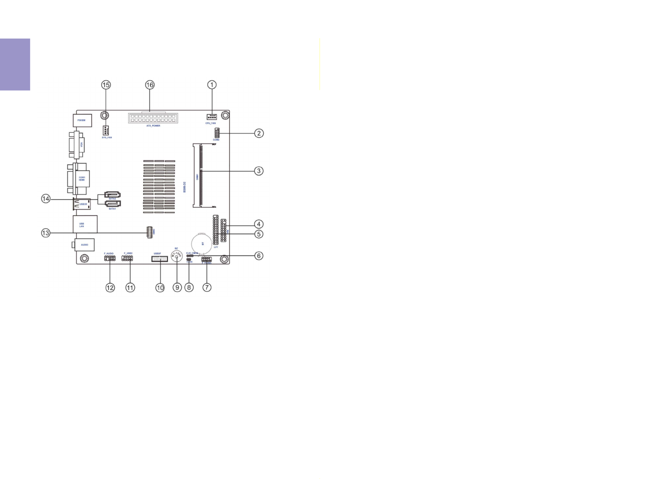
Motherboard Components
*BSWI-D2-J3710/BSWI-D2-J3160/BSWI-D2-J3060 MB image


5
BSWI-D2 USER MANUAL
Chapter 1
LABE
L
COMPONENTS
1. CPU_FA
N
4-pin CPU cooling fan connector
2. COM2 Onboard serial port header
3. DIMM1 204-pin DDR3L SDRAM SO-DIMM
4. TPM Trusted platform module header
5. LPT Onboard parallel port header
6. CLR_CMO
S
Clear CMOS jumper
7. F_PANE
L
Front panel switch/LED header
8. CASE Case open header
9. BZ Buzzer
10. USB3F Front panel USB 3.0 header
11. F_USB2 2*5 PIN Front USB 2.0 header
12. F_AUDIO Front panel audio header
13. EMMC EMMC header
14. SATA1~2 Serial ATA 6Gb/s connectors
15. SYS_FA
N
4-pin system cooling fan connector
16. ATX_POWER Standard 24-pin ATX Power connector
Table of Motherboard Components (BSWI-D2-J3710/BSWI-D2-J3160/BSWI-
D2-J3060 )

Chapter 1
6
BSWI-D2 USER MANUAL
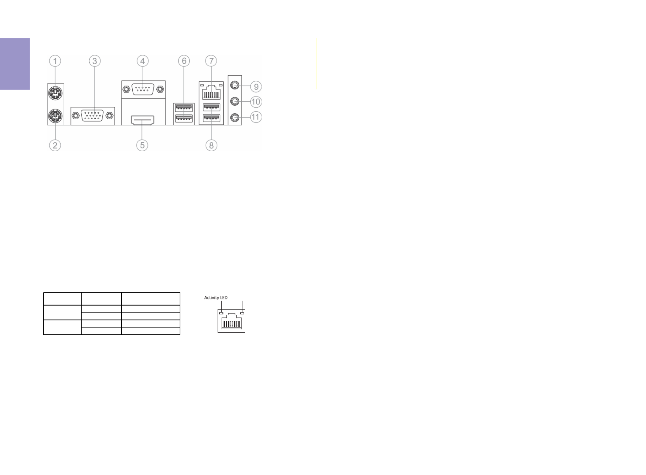
I/O Ports
1. PS/2 Mouse (green)
Use the upper PS/2 port to connect a PS/2 mouse.
2. PS/2 Keyboard (purple)
Use the lower PS/2 port to connect a PS/2 keyboard.
3. VGA Port
Connect your monitor to the VGA port.
5. HDMI Port
You can connect the display device to the HDMI port.
6. USB 3.0 Ports
Use the USB 3.0 port to connect USB 3.0 device.
7. LAN Port
Connect an RJ-45 jack to the LAN port to connect your computer to the Network.
8. USB 2.0 Ports
Use the USB 2.0 ports to connect USB 2.0 devices.
9. Line-in (blue)
It can be connected to an external CD/DVD player, Tape player or other audio
devices for audio input.
10. Line-out (green)
It is used to connect to speakers or headphones.
11. Microphone (pink)
It is used to connect to a microphone.
LAN LED Status Description
OFF No data
Orange blinking Active
OFF No link
Green Link
Activity LED
Link LED
Link LED
LAN Port
4. COM1 Port
Use the COM1 port to connect the serial devices such as mice or fax/modems.


Chapter 2
BSWI-D2 USER MANUAL
7
Chapter 2
Installing the Motherboard
2-1. Safety Precautions
2-2. Installing the motherboard in a Chassis
This motherboard carries a Mini ITX form factor of 170 x 170 mm. Choose a chassis
that accommodates this form factor. Make sure that the I/O template in the chassis
matches the I/O ports installed on the rear edge of the motherboard. Most system
chassis have mounting brackets installed in the chassis, which corresponds to the
holes in the motherboard. Place the motherboard over the mounting brackets and
secure the motherboard onto the mounting brackets with screws.
Follow these safety precautions when installing the motherboard:
• Wear a grounding strap attached to a grounded device to avoid damage
from static electricity.
• Discharge static electricity by touching the metal case of a safely grounded
object before working on the motherboard.
• Leave components in the static-proof bags.
• Always remove the AC power by unplugging the power cord from the power
outlet before installing or removing the motherboard or other hardware
components.
Do not over-tighten the screws as this can stress the motherboard.


Chapter 2
BSWI-D2 USER MANUAL
8
2-3. Checking Jumper Settings
To avoid the system instability after clearing CMOS, we recommend users to
enter the main BIOS setting page to “Load Default Settings” and then “Save
and Exit Setup”.
The following illustration shows the location of the motherboard jumpers. Pin 1 is
labeled.


Chapter 2
BSWI-D2 USER MANUAL
10
2-4-2. Connecting Optional Devices
Refer to the following for information on connecting the motherboard’s optional
devices:
No. Components No. Components
1 COM2 6 F_USB2
2 TPM 7 F_AUDIO
3 LPT 8 EMMC
4 CASE 9 SATA_1~2
5 USB3F ~ ~
1. COM2: Onboard Serial Port Header
Connect serial port extension brackets to these headers to add serial ports to your
system.


Chapter 2
BSWI-D2 USER MANUAL
12
4. CASE: Chassis Intrusion Detect Header
This detects if the chassis cover has been removed. This functiion needs a chassis
equipped with intrusion detection switch and needs to be enabled in BIOS.
Please make sure that the USB cable has the same pin assignment as indi-
cated above. A different pin assignment may cause damage or system hang-
up.
This Motherboard implements one USB 3.0 header supporting 2 extra front USB 3.0
ports, which delivers 5Gb/s transfer rate.
5. USB3F: Front Panel USB 3.0 header


Chapter 2
BSWI-D2 USER MANUAL
13
The motherboard has one 2*5-pin USB 2.0 header supporting two USB 2.0 ports.
Additionally, some computer cases have USB 2.0 ports at the front of the case. If you
have this kind of case, use auxiliary USB 2.0 connector to connect the front-mounted
ports to the motherboard.
6. F_USB2: 2*5-pin Front Panel USB 2.0 Header
Please make sure that the USB cable has the same pin assignment as
indicated above. A different pin assignment may cause damage or system
hang-up.
The front panel audio header allows the user to install auxiliary front-oriented
microphone and line-out ports for easier access. This header supports HD audio by
default. If you want connect an AC’97 front panel audio to HD onboard headers,
please set as below picture.
7. F_AUDIO: Front Panel Audio Header


Chapter 2
BSWI-D2 USER MANUAL
14
If you use AC’ 97 Front Panel, please don’ t tick off “Using Front Jack Detect ”. If you
use HD Audio Front Panel, please tick off the option of “Using Front Jack Detect ”.
* For reference only
If you use AC’97 Front Panel, please tick off the option of “Disabled Front Panel
Detect ”. ’ “ If you use HD Audio Front Panel, please don t tick off Disabled Front Panel
Detect ” .
* For reference only
AC’97 Audio Configuration: To enable the front panel audio connector to
support AC97 Audio mode.

Chapter 2
BSWI-D2 USER MANUAL
15
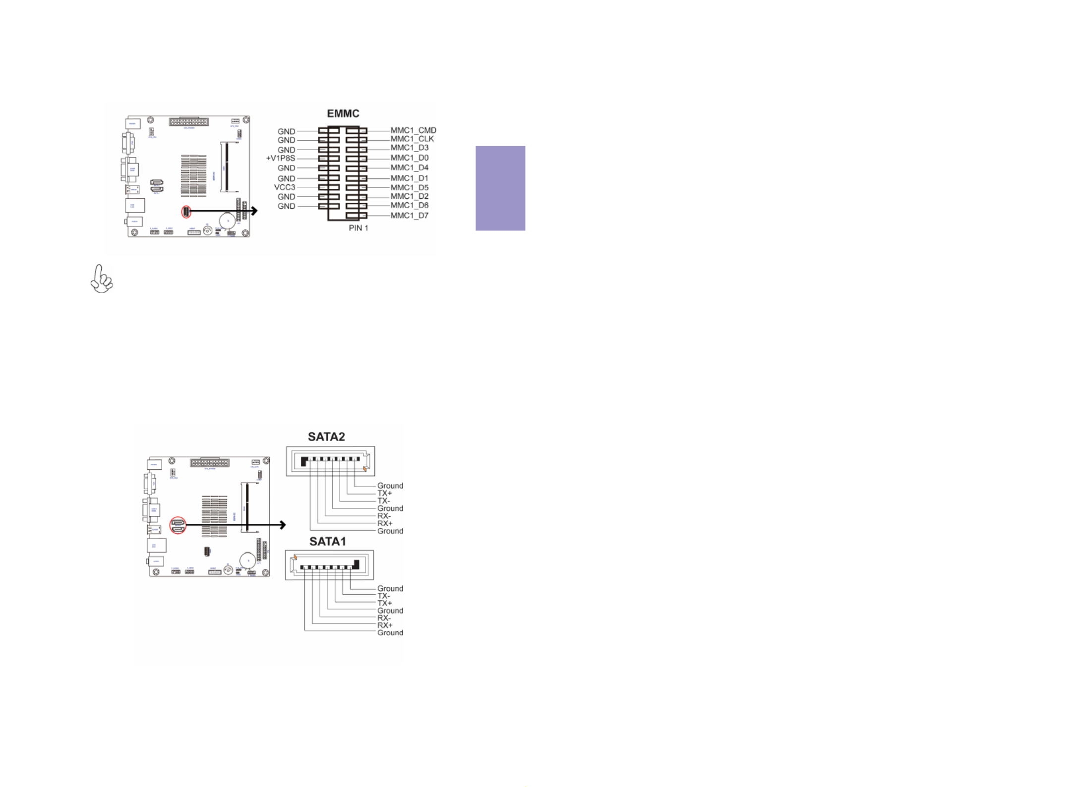
SATA 1~2 connectors support the Serial ATA 6Gb/s device, simpler disk drive cabling
and easier PC assembly. It eliminates limitations of the current Parallel ATA
interface. But maintains register compatibility and software compatibility with
Parallel ATA.
9. SATA1~2: Serial ATA Connectors
8. EMMC Header
The EMMC-BSW-32G card is not included in the package, you
can buy it separately and install.


Chapter 2
BSWI-D2 USER MANUAL
16
2-4-3. Installing a SATA Hard Drive
This section describes how to install a SATA Hard Drive.
About SATA Connectors
Your motherboard features two SATA connectors supporting a total of two drives.
SATA refers to Serial ATA (Advanced Technology Attachment) is the standard
interface for the IDE hard drives which are currently used in most PCs. These
connectors are well designed and will only fit in one orientation. Locate the SATA
connectors on the motherboard and follow the illustration below to install the SATA
hard drives.
Installing Serial ATA Hard Drives
To install the Serial ATA (SATA) hard drives, use the SATA cable that supports the Serial
ATA protocol. This SATA cable comes with a SATA power cable. You can connect either
end of the SATA cable to the SATA hard drive or the connector on the motherboard.
Refer to the illustration below for proper installation:
1 Attach either cable end to the connector on the motherboard.
2 Attach the other cable end to the SATA hard drive.
3 Attach the SATA power cable to the SATA hard drive and connect the other
end to the power supply.
* For reference only

Chapter 2
BSWI-D2 USER MANUAL
17
After you have installed the motherboard into a case, you can begin connecting the
motherboard components. Refer to the following:
2-4-4. Connecting Case Components
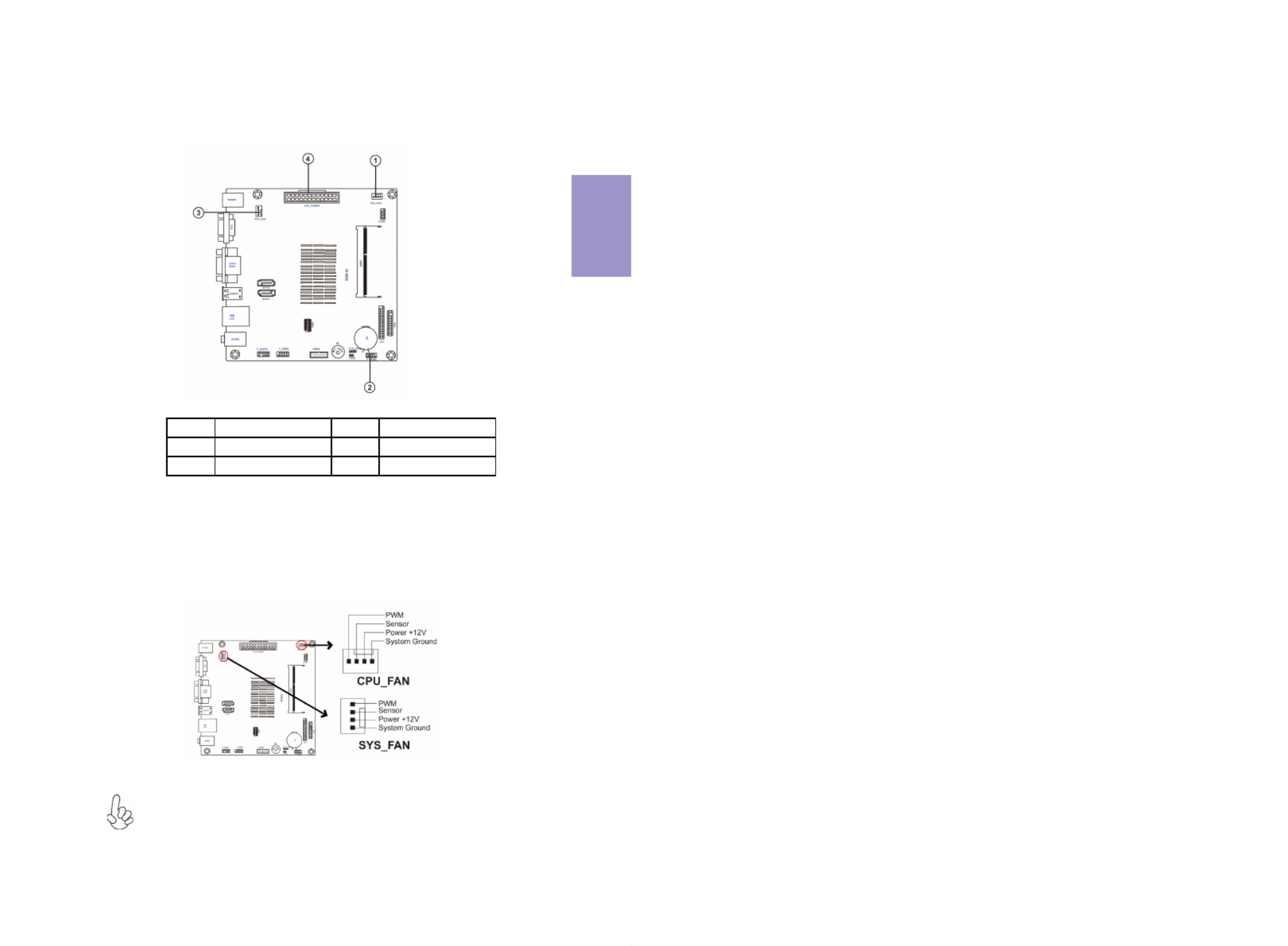
No. Components No. Components
1 CPU_FAN 3 SYS_FAN
2 F_PANEL 4 ATX_POWER
1 & 3. CPU_FAN (CPU Cooling FAN Connector) & SYS_FAN (System Cooling FAN
Connector)
Users please note that the fan connector supports the CPU cooling fan of 1.1A
~ 2.2A (26.4W max) at +12V.
Connect the CPU cooling fan cable to CPU_FAN.
Connect the system cooling fan connector to SYS_FAN.

Chapter 2
BSWI-D2 USER MANUAL
18
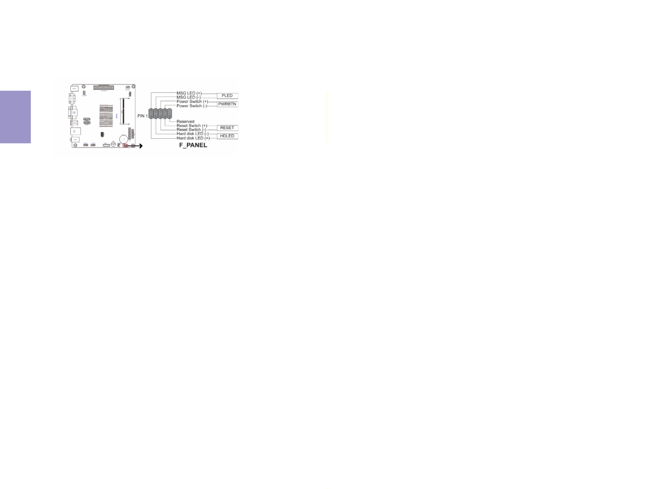
Hard Drive Activity LED
Connecting pins 1 and 3 to a front panel mounted LED provides visual indication that
data is being read from or written to the hard drive. For the LED to function properly,
an IDE drive should be connected to the onboard IDE interface. The LED will also
show activity for devices connected to the SCSI (hard drive activity LED) connector.
Power/Sleep/Message waiting LED
Connecting pins 2 and 4 to a single or dual-color, front panel mounted LED provides
power on/off, sleep, and message waiting indication.
Reset Switch
Supporting the reset function requires connecting pin 5 and 7 to a momentary-con-
tact switch that is normally open. When the switch is closed, the board resets and
runs POST.
Power Switch
Supporting the power on/off function requires connecting pins 6 and 8 to a momen-
tary-contact switch that is normally open. The switch should maintain contact for at
least 50 ms to signal the power supply to switch on or off. The time requirement is
due to internal de-bounce circuitry. After receiving a power on/off signal, at least
two seconds elapses before the power supply recognizes another on/off signal.
2. F_PANEL: Front Panel Header
The front panel header (F_PANEL) provides a standard set of switch and LED headers
commonly found on ATX or Micro ATX cases. Refer to the table below for information:

Specyfikacje produktu
| Marka: | ECS |
| Kategoria: | płyta główna |
| Model: | BSWI-D2-J3060 |
Potrzebujesz pomocy?
Jeśli potrzebujesz pomocy z ECS BSWI-D2-J3060, zadaj pytanie poniżej, a inni użytkownicy Ci odpowiedzą
Instrukcje płyta główna ECS

12 Stycznia 2025
12 Stycznia 2025
12 Stycznia 2025
12 Stycznia 2025
12 Stycznia 2025
12 Stycznia 2025
12 Stycznia 2025
11 Stycznia 2025
11 Stycznia 2025
11 Stycznia 2025
Instrukcje płyta główna
- płyta główna Supermicro
- płyta główna Gigabyte
- płyta główna Asus
- płyta główna MSI
- płyta główna NZXT
- płyta główna Biostar
- płyta główna Asrock
- płyta główna Sharkoon
- płyta główna Evga
- płyta główna Intel
- płyta główna Foxconn
- płyta główna Advantech
- płyta główna Elitegroup
- płyta główna EPoX
Najnowsze instrukcje dla płyta główna

8 Kwietnia 2025
8 Kwietnia 2025
3 Kwietnia 2025
3 Kwietnia 2025
3 Kwietnia 2025
3 Kwietnia 2025
2 Kwietnia 2025
2 Kwietnia 2025
2 Kwietnia 2025
30 Marca 2025