Instrukcja obsługi Digital Watchdog MegaPix DWC-MV74Wi28
Digital Watchdog
Kamera monitorująca
MegaPix DWC-MV74Wi28
Przeczytaj poniżej 📖 instrukcję obsługi w języku polskim dla Digital Watchdog MegaPix DWC-MV74Wi28 (84 stron) w kategorii Kamera monitorująca. Ta instrukcja była pomocna dla 12 osób i została oceniona przez 2 użytkowników na średnio 4.5 gwiazdek
Strona 1/84
User’s M’s aManunuaall7FS
nBefore installing and using the camera, please read this manual carefully.stalling and using the camera, please read this manual carefully.
to keep it handy Be sure to keep it handy for future reference.for future reference.
0(*$SL[03,QGRRU2XWGRRU
9DQGDO'RPH,3&DPHUD
':&09:L
':&0
':&0
9
:L
9
:
L
9
:
:L

Index
INTRODUCTION
Important Safety Information
'FBUVSFT
Part Name
%JNFOTJPOT
1SPEVDU"DDFTTPSJFT
INSTALLTION
Disassemble the Camera
Installation
*OTUBMMBUJPO using Mount Bolt & Nut
Cabling
*OTFSUJOH3FNPWJOHBO4%.FNPSZ$BSE
NETWORK SETUP
IP Installer
Quick Start of Network Connection DDNS
Registration
Guide to Network Environment Setup Case (A~D)
Port Forwarding
Starting IP Camera
Video & Audio Setup
Camera Setup
Network Setup
Trigger Action Setup
Events Setup
3FDPSE4FUVQ
Security Setup
System Setup
APPENDIX
Current TCP/IP Settings
Changing IP Address and Subnet mask
4QFDJGJDBUJPOT
FAQ
8BSSBOUZ
-JNJUT&YDMVTJPOT
WEB VIEWER SCREEN
2 Basic Screen
SETUP
Safety Information
This symbol indicates that dangerous voltage
consisting a risk of electric shock is present within
this unit.
Warning Precaution
This exclamation point symbol is intended to alert the
user to the presence of important operating and
maintenance (servicing) instructions in the literature
accompanying the appliance.
TO REDUCE THE RISK OF ELECTRIC SHOCK, DO NOT REMOVE COVER (OR BACK) NO USER SERVICEABLE
PARTS INSIDE. REFER SERVICING TO QUALIFIED SERVICE PERSONNEL.
CAUTION:
CAUTION
RISK OF ELECTRIC SHOCK.
DO NOT OPEN.
To prevent damage which may result in fire or electric shock
hazard, do not expose this appliance to rain or moisture.
WARNING
Be sure to use only the standard adapter that is specified in
the specification sheet. Using any other adapter could cause
fire, electrical shock, or damage to the product.
Incorrectly connecting the power supply or replacing battery
may cause explosion, fire, electric shock, or damage to the
product.
Do not connect multiple cameras to a single adapter.
Exceeding the capacity may cause excessive heat generation
or fire.
Securely plug the power cord into the power receptacle.
Insecure connection may cause fire.
When installing the camera, fasten it securely and firmly.
A falling camera may cause personal injury.
Do not place conductive objects (e.g. screw drivers, coins,
metal items, etc.) or containers filled with water on top of
the camera. Doing so may cause personal injury due to fire,
electric shock, or falling objects.
Do not install the unit in humid, dusty, or sooty locations.
Doing so may cause fire or electric shock.
If any unusual smells or smoke come from the unit, stop
using the product. Immediately disconnect the power sorce
and contact the service center. Continued use in such a
condition may cause fire or electric shock.
If this product fails to operate normally, contact the nearest
service center. Never disassemble or modify this product in
any way.
When cleaning, do not spray water directly onto parts of the
product. Doing so may cause fire or electric shock.
WARNING
1.
2.
3.
4.
5.
6.
7.
8.
9.
10.
Precaution
Operating
t Before using, make sure power supply and all other parts are
properly connected.
t While operating, if any abnormal condition or malfunction
is observed, stop using the camera immediately and contact
your dealer.
Handling
tDo not disassemble or tamper with parts inside the camera.
tDo not drop the camera or subject it to shock or vibration as
this can damage the camera.
tClean the clear dome cover with extra care. Scratches and
dust can ruin the quality of the camera image.
Installation and Storage
tDo not install the camera in areas of extreme temperature,
exceeding the allowed range.
tAvoid installing in humid or dusty environments.
tAvoid installing in places where radiation is present.
tAvoid installing in places where there are strong magnetic
tAvoid installing in places where the camera would be subject
to strong vibrations.
tNever expose the camera to rain or water.

Important Safety Instructions
1. Read these instructions. - All these safety and operating instructions should be read before the product is
installed or operated.
2. Keep these instructions. - The safety, operating and use instructions should be retained for future reference.
3. Heed all warnings. - All warnings on the product and in the operating instructions should be adhered to.
4. Follow all instructions. - All operating and use instructions should be followed.
5. Do not use this device near water. - For example: near a bath tub, wash bowl, kitchen sink, laundry tub, in a wet
basement; near a swimming pool; etc.
6. Clean only with dry cloth. - Unplug this product from the wall outlet before cleaning. Do not use liquid cleaners.
7. Do not block any ventilation openings. Install in accordance with the manufacturer’s instructions. - Slots and
openings in the cabinet are provided for ventilation, to ensure reliable operation of the product, and to protect it
from over-heating. The openings should never be blocked by placing the product on bed, sofa, rug or other similar
surface. This product should not be placed in a built-in installation such as a bookcase or rack unless proper
ventilation is provided and the manufacturer’s unstructions have been adhere to.
8.
that produce heat.
9. Do not defeat the safety purpose of the polarized or grounding-type plug. A polarized plug has two blades with
one wider than the other. A grounding type plug has two blades and a third grounding prong. The wide blade
electrician for replacement of the obsolete outlet.
10. Protect the power cord from being walked on or pinched particularly at plugs, convenience receptacles, and
the point where they exit from the apparatus.
11.
12.
manufacturer, or sold with the apparatus. When a cart is used, use
caution when moving the cart/apparatus combination to avoid
injury from tip-over.
13. Unplug this apparatus during lightning storms or when unused for long periods of time.
14.
in any way, such as power supply cord or plug is damaged, liquid has been spilled or objects have fallen into the
apparatus, the apparatus has been exposed to rain or moisture, does not operate normally, or has been
dropped.

Disposal of Old Appliances
1. When this crossed-out wheel bin symbol is attached to a product it means the product is covered by
the European Directive 2002/96/EC.
2. All electrical and electronic products should be disposed of separately form the municipal waste
stream stream in accordance to laws designated by the government or the local authorities.
3. The correct disposal of your old appliance will help prevent potential negative consequences for
the environment and human health.
waste disposal service or the shop where you purchased the product.
This equipment has been tested and found to comply with the limits for a Class A digital device, pursuant to part 15 of the FCC Rules.
These limits are designed to provide reasonable protection against harmful interference when the equipment is operated in a commercial environment.
This equipment generates, uses, and can radiate radio frequency energy and, if not installed and used in accordance with the instruction manual, may cause
harmful interference to radio communications. Operation of this equipment in a residential area is likely to cause harmful interference in which case the user
will be required to correct the interferenece at his own expense.
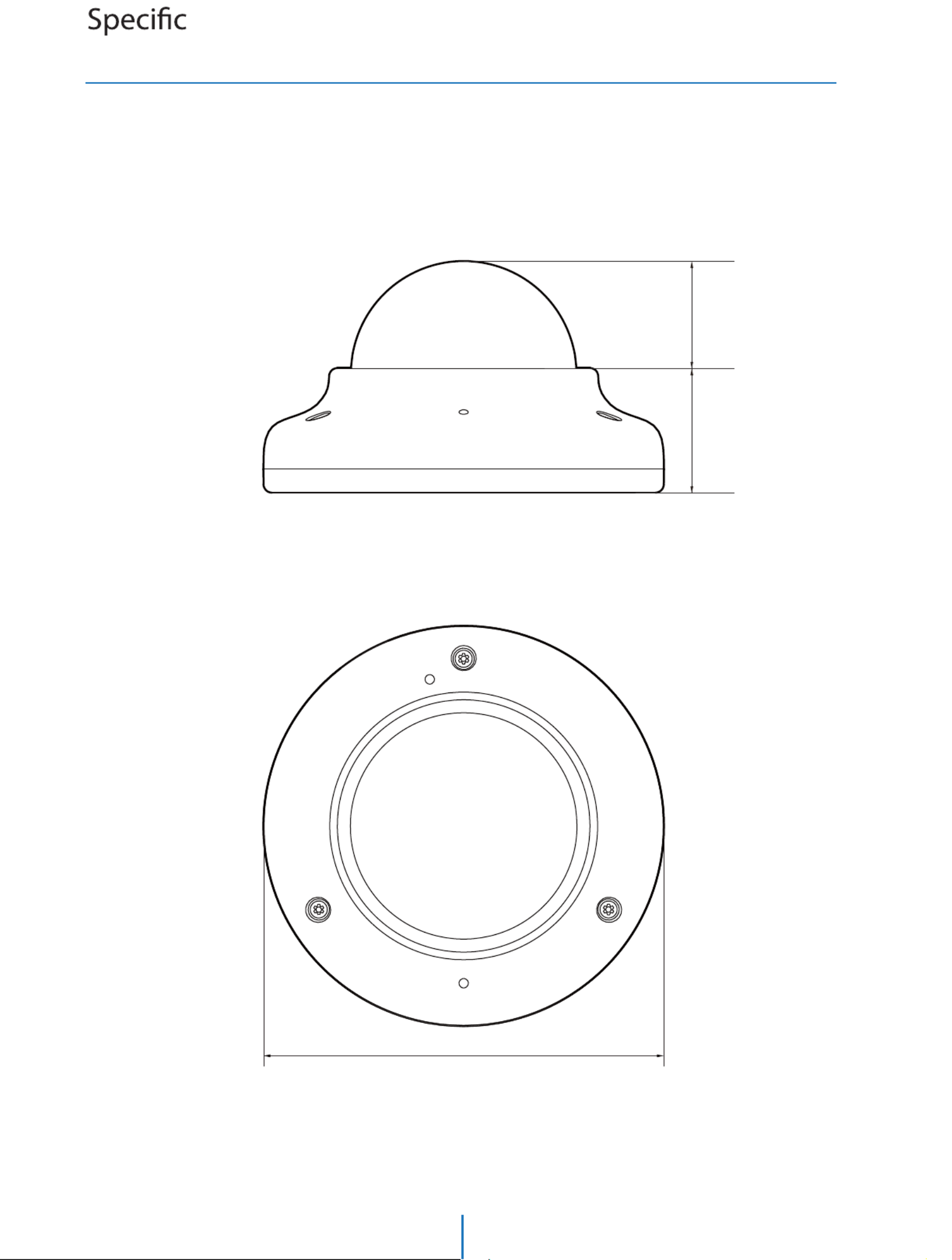
Unit: m*ODIN
Dimension
ations -
105 NN
NN32.5
NN28.2
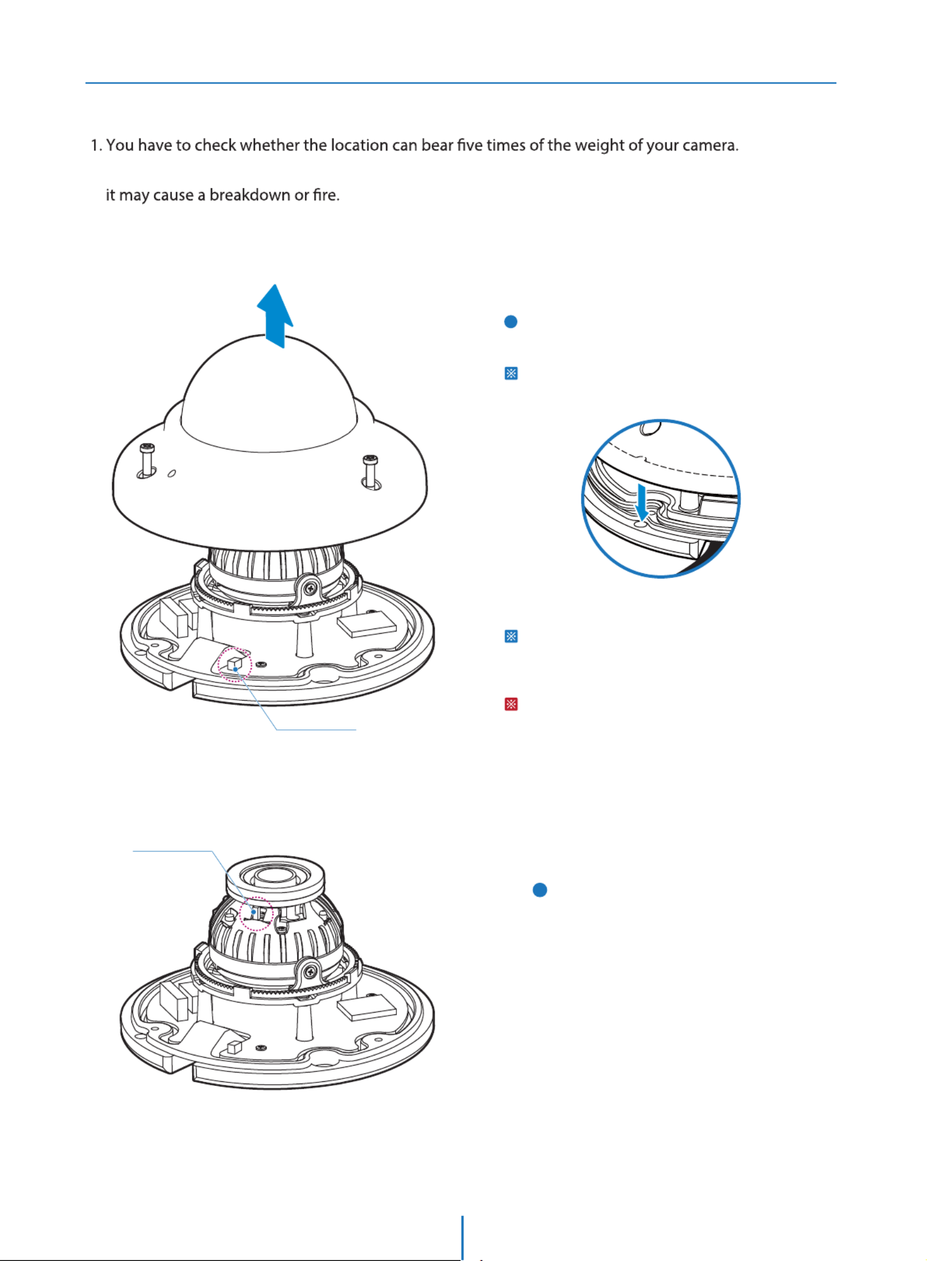
Disassemble the camera
Installation -
Before installing your camera, you have to read the following cautions.
2. Don’t let the cable to be caught in improper place or the electric line cover to be damaged. Otherwise
3. When installing your camera, don’t allow any person to approach the installation site. If you have any
valuable things under the place, move them away.
Detach the dome cover by torx wrench provided from
bottom case before installation the camera.
Match the one screw hole on the dome cover and
camera bottom specially.
1
Reset to the Factory Default
Press the reset button for 5 seconds to return the setup
to the factory default.
Warning:
If you press the ‘Reset’ button, you will lose all setting
data. If needed, please, make a note for further installation.
LED ON/OFF
The camera has a manual IR switch, located under
the camera’s lens. You can use this switch to
manually turn the IR LED board on or o according to
the installation needs.
2
Reset Button

7
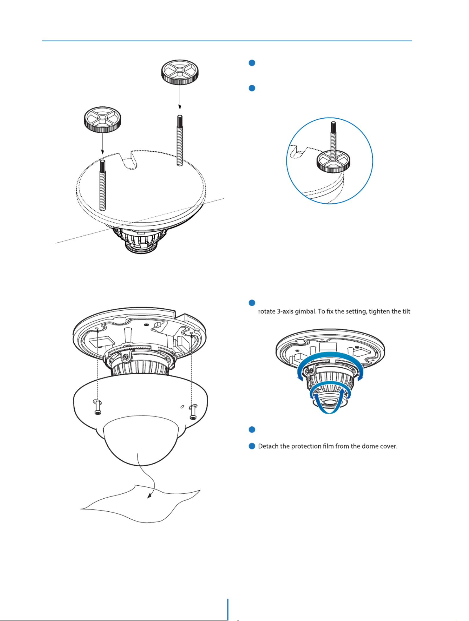
Attach the dome cover to the bottom case.
1
2
3
4
Disassemble the camera. See the section ‘Installation -
Disassemble the camera’ for details.
Using the template sheet, make the cabling hole on
the wall/ceiling.
Connect the network cable and power cable
respectively. See the section 'Installation - Cabling' for
details.
on the ceiling.
To achieve desired view direction and orientation,
stopper screw.
5
6
ab
c
Put the Lan cable into (a), then (b) will be assembled to (a)
without making any space.
Installation
Installation -
3
2
6
5
4
3
3
3
2
Template Sheet
7

Installation -
Installation Using Mount Bolt & Nut
Template Sheet 1Disassemble the camera. See the section ‘Installation -
Disassemble the camera’ for details.
Using the template sheet, make the cabling holes on
the ceiling panel.
Insert the 2 mount bolts into bottom case of camera.
3
2
Installation -
Installation Using Mount Bolt & Nut
5
Insert the mount bolts into template holes after
connecting the cable.
Fix the bottom case by tightening mount nuts to
mount bolts on the ceiling panel.
4
7
8
6To achieve desired view direction and orientation,
Attach the dome cover to the bottom case.
stopper screw.

Cabling
Installation -
Power
Two Options
Use a PoE-enabled switch to connect data and power through a single cable and begin viewing and recording images instantly.
A non-PoE switch will require an adaptor for power transmission.
Ethernet cableEthernet cable
2. Using a Non-PoE Switch
If a PoE-enabled switch is not used, use a power adaptor
for power transmission and non-PoE switch for data
transmission.
Follow the illustrations below to connect the camera
without a PoE-enabled Switch.
1. Using a PoE-Enabled Switch
The Camera is PoE-compliant, allowing transmission of
power and data via a single Ethernet cable.
power, record, or control the camera. Follow the illustration
below to connect the camera to a PoE-enabled switch using
an Ethernet cable.

Inserting/Removing a SD Memory Card
Installation -
1Insert the SD card in the arrow direction.
Don’t insert the SD memory card while it’s upside down by force.
Otherwise, it may damage the SD memory card.
Use the tweezers when inserting or picking out the SD card.
2Removing a SD Memory Card Gently press down on the
exposed end of the memory card as shown in the diagram
to eject the memory card from the slot.
Pressing too hard on the SD memory card can cause the card to
shoot out uncontrollably from the slot when released.
If you have saved data in the SD memory card, removing the SD
memory card prior to setting record to OFF will cause damage to
the data stored in the card.
Micro
The memory card is an external data storage device
that has
to record and share video, audio, and text data using
digital devices.
Recommended SD Card Specication ( )Not Included
- Type: Micro SD (SD/SDHC/SDXC)
- Manufacturer: Transcend, Kingston, Toshiba, SanDisk
- Capacity: 4GB~128GB
- Class: UHS-I U3 Class 10
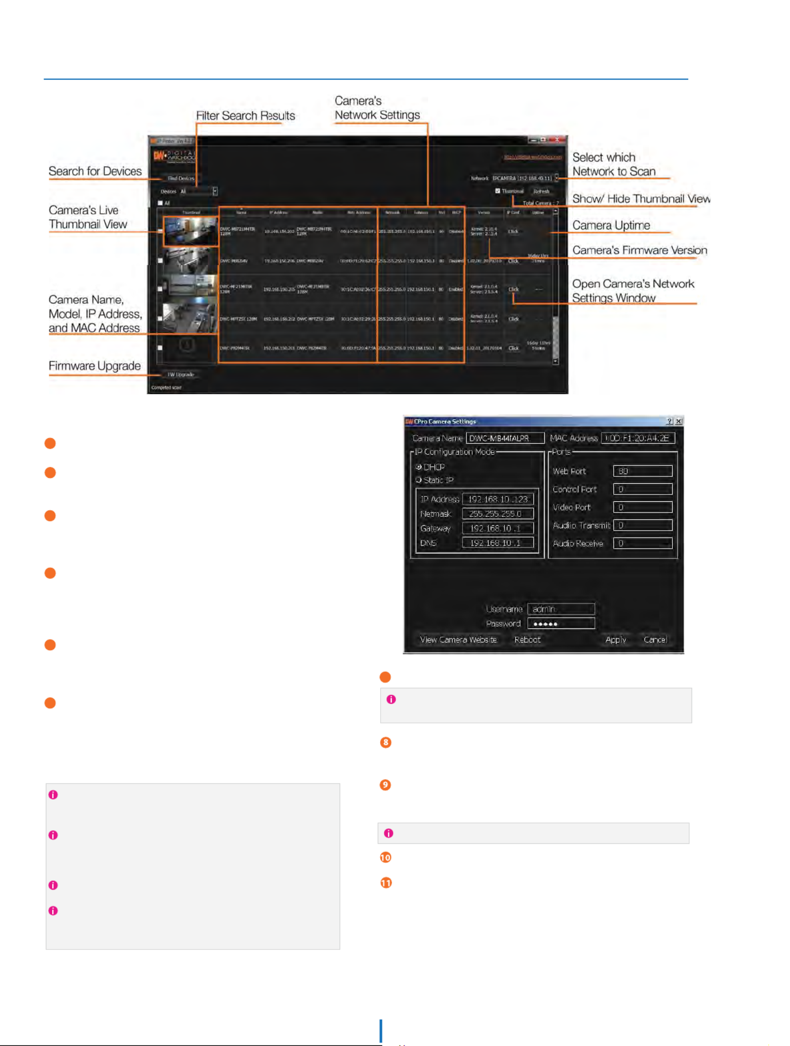
Network Setup -
DW IP Finder™
To save the changes made to the camera's settings, input ID and
PW of the camera for authentication.
If the camera needs to be rebooted after the settings were changed,
press the 'Reboot' button. The camera will power cycle and will
appear back in the search results once the reboot is complete.
Click ‘Save’ to save changed values.
To update the camera's rmware from the DW IP Finder™,
click on the rmware tab, upload the rmware le and
select the cameras to update. You can update multiple
cameras at the same time.
4FMFDUA%)$1JGUIFJOUFSOFUTFSWJDFJTEZOBNJD*1UPBMMPXUIF
DBNFSBTOFUXPSLJOGPSNBUJPOUPCFGJMMFEPVUBVUPNBUJDBMMZ
4FMFDUA4UBUJDUPNBOVBMMZFOUFSUIFDBNFSBTOFUXPSL
JOGPSNBUJPO:PVDBOBEKVTUUIFDBNFSBTOFUXPSLUZQF*1
BEESFTTTVCOFUNBTL(BUFXBZBOE%/4JOGPSNBUJPO
$ontact your network administrator for more information.
5IFDBNFSBhTEFGBVMUOFUXPSLJOGPSNBUJPOJT
%FGBVMU5$1*1JOGPSNBUJPO
*1%)$1
A ‘Port Forwarding’ has to be set in your network’s router for
external access to the camera.
Default ID / PW : admin / admin
To view the camera's web client, click on 'View Camera Website'.
(PUPIUUQXXXEJHJUBMXBUDIEPHDPN
4FBSDIGPSA*1'JOEFSPOUIFRVJDLTFBSDICBSBUUIFUPQ
PGUIFQBHF
5IFMBUFTU%8*1'JOEFSTPGUXBSFXJMMBQQFBSJOUIF
TFBSDISFTVMUT$MJDLPO
UIFMJOLUPEPXOMPBEUIFGJMFUPZPVSDPNQVUFS
5IFTPGUXBSFXJMMTDBOZPVSOFUXPSLGPSBMMTVQQPSUFE
DBNFSBTBOEEJTQMBZUIFSFTVMUTJOUIFUBCMF"MMPXVQUP
TFDPOETGPSUIF%8*1'JOEFSUPGJOEUIFDBNFSBPOUIF
OFUXPSL
$IFDLUIFCPYOFYUUPh%JTQMBZ$BNFSB5IVNCOBJMhUP
WJFXB+1&(JNBHFPGUIFDBNFSBhTWJFXOFYUUPUIF
DBNFSBOBNFPOTVQQPSUFENPEFMT
4FMFDUBDBNFSBGSPNUIFMJTUCZEPVCMFDMJDLJOHPOUIF
DBNFSBTJNBHFPSDMJDLJOHPOUIFA$MJDLCVUUPOVOEFSUIF
*1$POGDPMVNO5IFDBNFSBTOFUXPSLJOGPSNBUJPOXJMM
BQQFBS*GOFDFTTBSZZPVDBOBEKVTUUIFDBNFSBT
OFUXPSLUZQF

Quick Start of Network Connection
Network Setup -
Please follow the steps below to complete
the initial setup of the network function.
1.
Open the IP Installer on a PC, then search for the IP camera.
If multiple numbers of camera are connected it should be
distinguished by the mac address of the Camera.
Click the Camera IP, and connect to the WEB PAGE.
2.
3.
4.
Default ID/Password to access IP Camera are both the
word: admin.
5.
Familiarize yourself with the Viewer Interface Screen.6.
please install VLC to display live video.7.
The IP setting can be set to ‘STATIC’ at IP Installer or web
viewer followed by Setup -> Network -> Network Settings
8.
If you have a DHCP server, it will automatically set the Camera IP.
If you do not have a DHCP server, Camera IP is set to 192.168.1.80
after one minute. In this case, PC IP must be changed to the IP to
be able to access the 192.168.1.80.
Please do not power on the IP Camera until instructed.
Explorer.
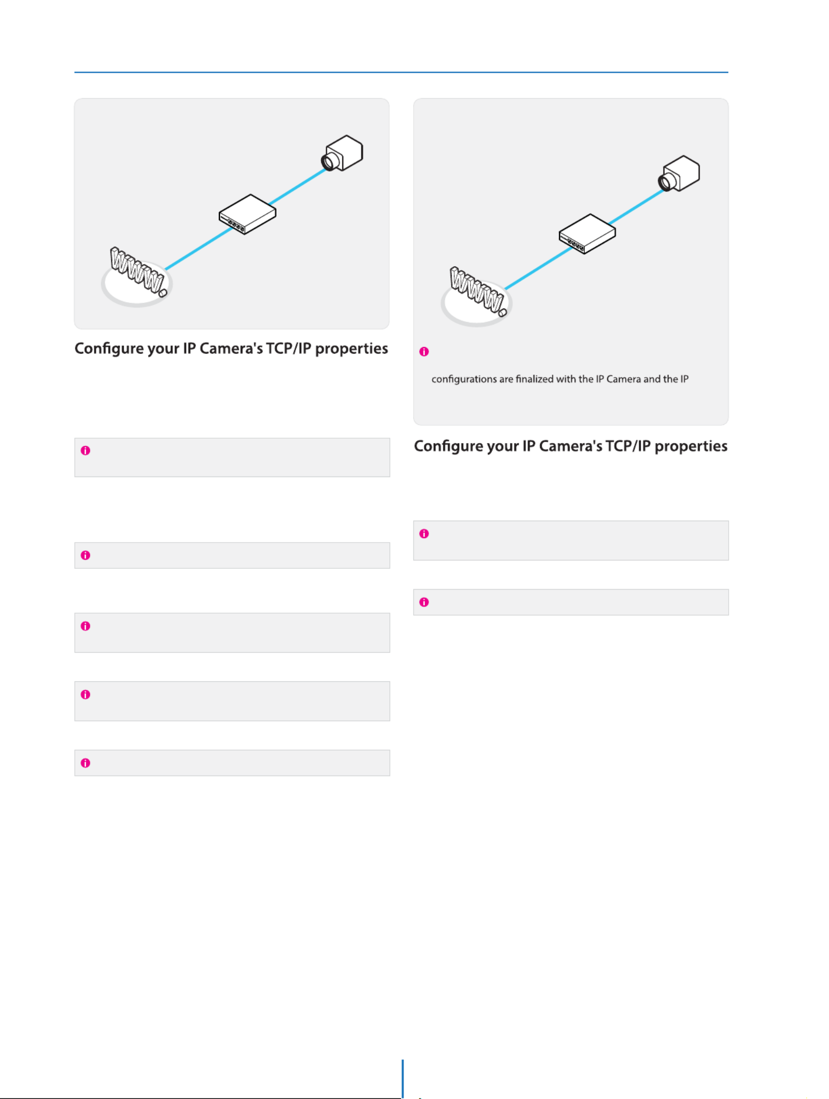
If connecting the IP Camera directly to a modem, power down
and reset the modem. Leave the modem powered down until
con tions ar nalized with the IP Camera and the IP Camera
has been correctly connected to the modem.
If the IP Camera is connected to a network which utilizes a
router, you must have Port Forwarding co ured on your
personal router to forward all ports to the IP address you
have assigned the IP Camera.
(if necessary), you may access your IP Camera on your local
network by opening Internet Explorer and specifying the IP
address and Web Port that you have assigned to the IP
Camera.
9.
10.
Example: http://192.168.0.200:8888
If you leave your Web Port set to 80, you don’t need to specify
the port in the Address Bar to access to your IP Camera.
Access your IP Camera via the Internet :
If you use a static IP address assigned by your ISP
1) Open Internet Explorer.
2) Type the IP of the IP Camera.
3) If you use a router, type the routers’ static IP and the web port
number of the IP Camera.
If you have a dynamic address provided by your ISP
1) Open Internet Explorer and visit the DDNS website.
2) Register the IP Camera.
3) Reboot the IP Camera.
4) Give the DDNS server 10 minutes to locate your IP Camera’s
IP information.
5) Click the refresh button in the Internet Explore.
6) After your camera is connected, select your camera.
11.

DDNS Registration
Network Setup -
If you have DYNAMIC IP service from your
Internet Service Provider (ISP), you can’t tell
the current IP address of the IP Camera.
To solve this problem, you have to register to
our DDNS service.
A t, you have to check if you are using
dynamic addressing. If so, register your IP
Video Server on our DDNS website before you
c re, setup, or install the IP Camera.
Even though your IP is not dynamic, you will
just remember ‘hostname.dyndns.com/gate1’
instead of complicated series of numbers like
http://201.23.4.76:8078.
For more details, contact our Support Center.
To use a public DDNS called ‘dyndns’ or ‘no-ip’, refer to the detail
information on how to use the service.
(Visit the web site : http://www.dyndns.com or
http://www.no-ip.com)
Guide to Network Environment
Network Setup -
Please congure the IP Camera at the
installation site. You must determine your
network scenario in order to congure the IP
Camera with the proper TCP/IP settings.
This tutorial will guide you through the
process. Before actually conguring the IP
Camera, determine settings to be applied.
Record those settings to be used to congure
your IP Camera for reference.
When conguring your IP Camera, treat the
IP Camera as another PC on your network.
You will assign it several addresses and other
TCP/IP properties to match your current
network.
This step-by-step tutorial will teach what IP
addresses and network congurations should
be assigned based on the network scenario.
If you were not given any IP addresses or the ISP was responsible
for the setup and installation of your Internet connection, go to
step 2.
If you are not using a router on your network, your ‘Current TCP/IP
Settings’ (from the previous section) and ‘Assigned IP Addresses
from My ISP’ will be exactly the same.
Before you begin, locate any information and settings
received from your Internet Service Provider (ISP). You may
need to refer to these IP addresses at a later time during the
conguration.
1.
You must determine whether the IP address is STATIC or
DYNAMIC. At this moment, you are only concerned about the
ISP. Did they provide you with a STATIC or DYNAMIC address?
If you are unsure, contact your ISP.
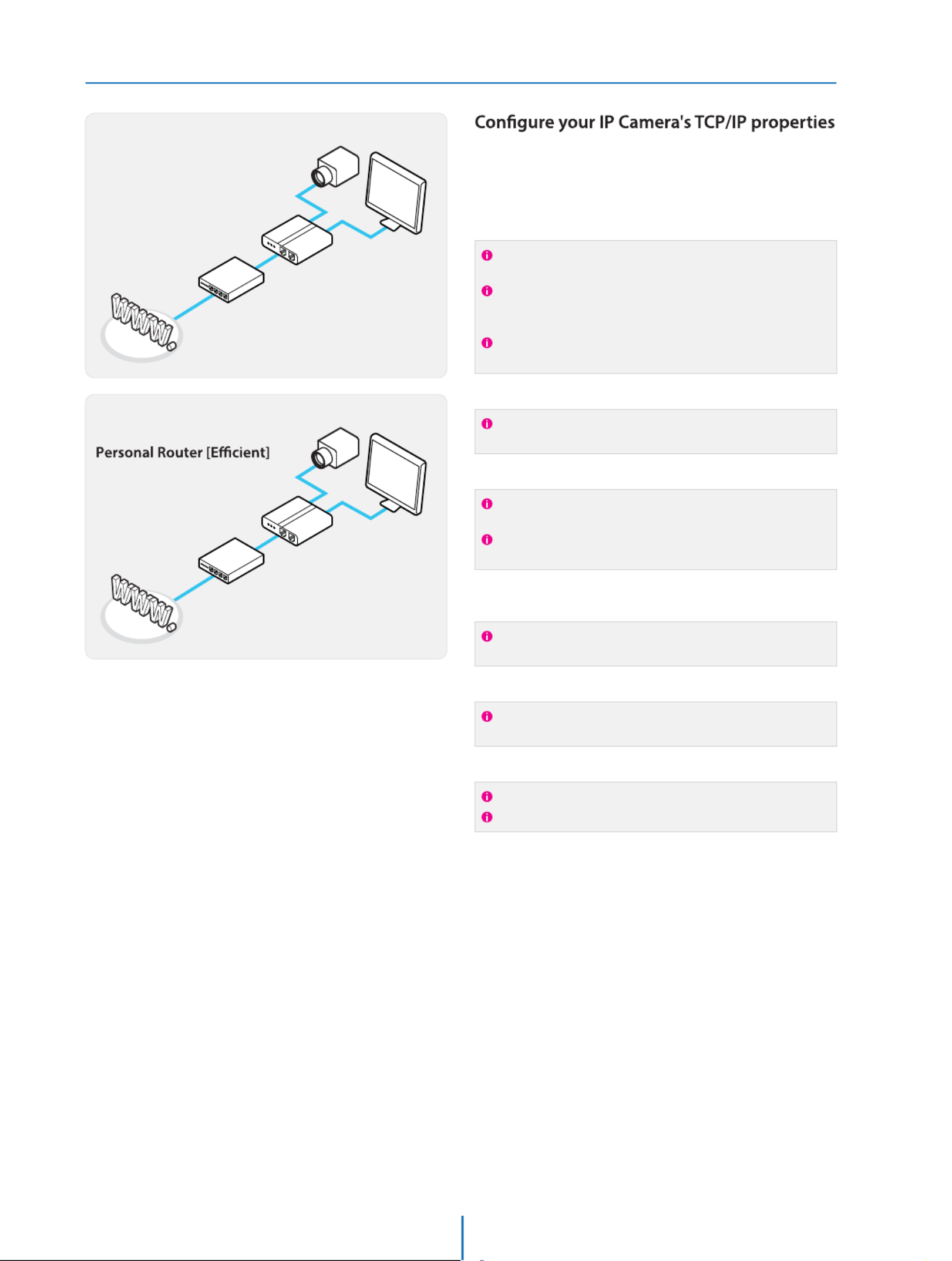
Congure your IP Camera’s TCP/IP settings for network
connectivity by selecting Setup from the main interface and
selecting TCP/IP located on the left of the Setup screen.
If prompted for ID and Password, use ‘admin’ for both entries.
The default web port number is 80. If port 80 is blocked by
the ISP, a value between 1025 ~ 60000 should be used. If TCP
port 80 is blocked, consult the ISP
2.
3.
4.
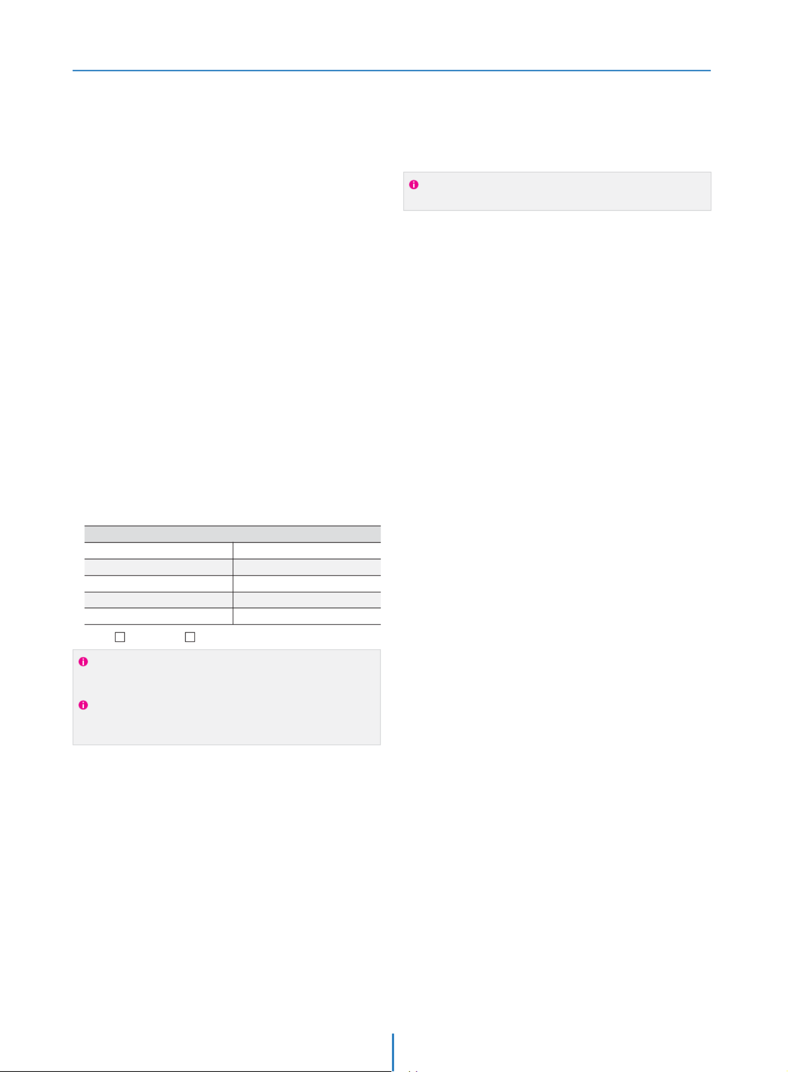
Current TCP/IP Settings
IP Address
Subnet Mask
Default Gateway
Primary DNS Server
Secondary DNS Server (Option)
Static Dynamic
5. The following descriptions are several basic network
scenarios. Determine which scenario describes your network.
If your network does not match one of the scenarios below
and you are unsure how to setup your IP Camera, contact
your network administrator and then call our Support Center.
You cannot control the rectangular gray areas and only the ISP
has access to the devices.
Setup Case A, B
Network Setup -
Case A:
Dynamic IP +
Personal Router [Most SOHO]
Personal Router
W/Intergrated Switch
Cable/xDSL Modem
(ISP Provided)
Phone Line
or CATV
PC
Internet
Case B:
Static(Fixed) IP +
PC
Personal Router
W/Intergrated Switch
Gateway or Router
at ISP
Public Line
Internet
as follows :
STATIC (even though you have Dynamic IP from
your ISP, use STATIC on the IP Camera)
Network Type :1.
A private IP address such as
192.168.0.200 (Example)
Internet Address :2.
You need to assign an IP address to the IP Camera just as you do
with PC.
The IP address you assign must be unique to your network and
match your network as well. For information on how to choose
a unique IP and match your network, read the FAQ.
The IP address you assign must be a private IP. For information
on how to choose a private IP please, read the FAQ.
255.255.255.0 (Example)
192.168.0.1 (Example)
Subnet Mask :3.
You must use the same subnet mask as the one you noted under
‘Current TCP/IP Settings’.
Default Gateway :4.
This IP address must be the IP address of your router.
(private or LAN side)
Use the same Default Gateway you noted under ‘Current TCP/IP
Settings’.
Use the 1st DNS Server from ‘Assigned IP
Address from My ISP’.
Preferred DNS Server :5.
Use the DDNS server.
DDNS Server :6.
This is the same site you will register later to accommodate
dynamic IP from your ISP.
8888Web Port :7.
Do not use the default port 80 as this number must be changed.
You may select any number between 1025 ~ 60000.
If you did not receive any IP addresses from your ISP, contact
the ISP and acquire the IP address of their DNS server.
Camera
Camera
Setup Case C, D
Network Setup -
To connect the IP Camera directly to a modem, power down
and reset the modem. Leave the modem powered down until
Camera has been connected correctly to the modem. Then
power on the modem, followed by the IP Camera.
Cable/xDSL Modem
(ISP Provided)
Phone Line
or CATV
Internet
Internet
Public Line Gateway or
Router at ISP
STATICNetwork Type :1.
A static IP address received from your ISP such
as 24.107.88.125 (Example)
Internet Address :2.
You need to assign an IP address to the IP Camera just as you do
with PC.
Subnet mask assigned from your ISP such as
255.255.255.240 (Example)
24.107.88.113 (Example)
Subnet Mask :3.
Default Gateway :4.
Use the assigned default gateway from your ISP
Use the 1st DNS Server from ‘Assigned IP
Address from My ISP’
Preferred DNS Server :5.
Use the DDNS server
DDNS Server :6.
This is the same site you will register later to utilize our DDNS
service.
80Web Port :7.
You may select any number between 1025 ~ 60000.
If you have not received any IP addresses from your ISP, contact
them to acquire the IP address of their DNS server.
DYNAMICNetwork Type :1.
Use the DDNS serverDDNS Server :2.
This is the same site you will register later to accommodate
dynamic IP from your ISP.
80Web Port :3.
You may select any number between 1025 ~ 60000.
as follows :
as follows :
Case C:
Static(Fixed) IP [Dedicated line directly
to the IP Camera]
Case D:
Dynamic IP + DSL/Cable Modem [Connected
directly to the IP Camera]
Camera
Camera

Port Forwarding
Network Setup -
After entering the correct TCP/IP settings, you
are ready for ‘Port Forwarding’(Cases A, B).
Please record the TCP/IP settings of your IP Camera for future
reference. You may need this information to access your IP
1.
After clicking ‘Apply’, the system will prompt for a reboot.
Please allow the system 50 seconds to reboot and accept the
changes. After 50 seconds, close the con ration screen.
The view will display ‘Trying to Reconnect’. If the ACTIVE light
, the IP Camera has rebooted. After the system
reboots completely, remove the power supply from the
unit and close Internet Explorer.
Return your PC/Laptop TCP/IP properties to their original
settings.
Before installing the IP Camera, you must use ‘Port
Forwarding’ on your personal router (Cases A, B).
You will need to forward 1 ports:
t Web Port
All the ports will be forwarded to the IP address you
assigned to the IP Camera.
In the example above, you would forward:
t
2.
3.
4.
IP Camera TCP/IP Settings
IP Address
Subnet Mask
Default Gateway
Preferred DNS Server
DDNS Server
Web Port
For information on how to use ‘Port Forwarding’, please read
Appendix C.

Starting IP Camera
Network Setup -
After forwarding correctly the Web Port,
through your router (if applicable), install the
IP Camera in a proper location.
Locate the serial number located on the label attached to the
bottom of the IP Camera, you will need this for DDNS
registration.
Connect the IP Camera to your router or cable/DSL modem
(per your network scenario) via a Cat5/5e UTP Ethernet
network cable.
Supply power to the IP Camera.
After 1 minute, verify the IP Camera indicators:
t-*/,Flickering/Solid
(if necessary), access your IP Camera on your local network
by opening Internet Explorer and specifying the IP address
and Web Port assigned to the IP Camera.
1.
2.
3.
4.
5.
Access your IP Camera via the Internet :6.
Examples: http://192.168.0.200:8888 or http://24.106.88.123
If you left your Web Port set to 80, do not need to specify the
port in the Address Bar to access the IP Camera.
If you use Case B, C
1) Open Internet Explorer.
2) Type the IP of the IP Camera.
If you use Case A, D
1) Open Internet Explorer.
2) Visit the DDNS website.
3) Register the IP Camera.
4) Give the DDNS server 10 minutes (MAX) to locate your IP
Camera’s IP information. You may reboot the server to send an
immediate request to our DDNS server.
5) After your camera is connected, select your camera.
The di ence between B and C is that B needs to set the port
forwarding.
Since the type of DDNS s from the service type, refer to
the related service site.

Basic Screen
Web Viewer Screen -
3
2
4
5
6
7
Web viewer is optimized with explorer10 or above version
and Firefox.
Live video display. This is the region for live video stream
from the camera.
Setup popup button. Click it to open the Setup page to
setup details of IP camera like Video, Network, Events,
System and etc. See the section ‘Setup’ .
3When the image goes unsmoothly because of bad network
connection, it stored image during setup time and shows
the image on the live view screen.
User will see the delayed images as much as setup time.
2
1
4Channel Select button. Select a stream produced from the
camera between Stream 1 ~ 3 to display it in the live view
screen.
Refer the ‘Setup > Video & Audio > Video’ to setup the Video
Stream.
Event Alert Icon ( ) appears if ‘Motion Detection’ is activated.
Below “Menu”is supported in accordance with models.
PTZ Control
This camera model does not supports the zoom and focus.
Preset
Does not support.
Alarm Input
Does not support.
Motion
It shows the Motion event status.
6
Camera Time
Display the camera time.
7
5
Speaker Control
Does not support.
Relay Out
Does not support.
1
If VLC is not installed or VLC plugin is not supported (Chrome),
Live buering and Channel select menu on 3, 4 will be changed
to Live Viewer menu, and then if HTML5(MJPEG) is selected on
Live Viewer menu, then you can check the video.

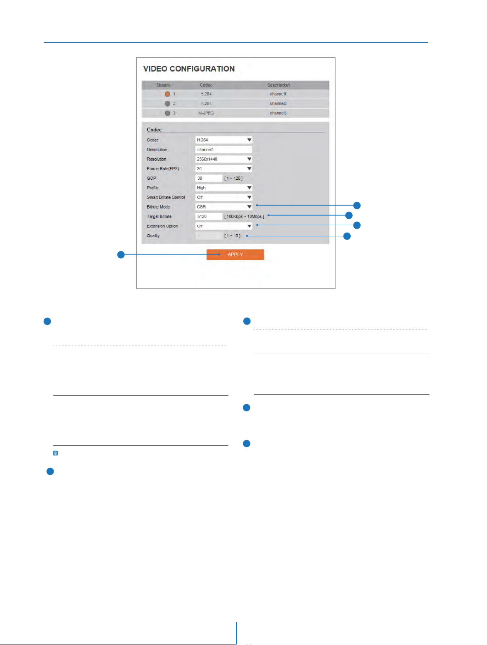
Video Configuration
Setup - Video & Audio Setup
1
2
3
5
4
1
2
Live Video Channel Setup
The video can be congured to variety settings with a
combination of codec and resolution.
The camera performance has to be considered when setting
multiple channels. This eects on the performance of the
camera.
Codec
Choose the video codec. According to the selected codec,
the subcategories can be changed automatically.
When MJPEG codec is selected, it will be able to set whether
to use the relevant channel for image transfer.
3Description
Input the additional description about the selected channel.
Max. 30 alphabets are allowed(Including space). For the
description, English Alphabets, numbers and special
characters ( - _ @ . ) can be used.
4Resolution
Select the video resolution.
Available resolution can be depends on the codec setup between
the channels.
5Frame Rate
Select the maximum Frame Rate.
Available Frame Rate can be dierent although same codecs
were set up.
<Resolution of Video Format>
720p/i
SVGA
VGA
4CIF
PAL
1280 x 720
NTSC
1280 x 720
1080p/i
4M
3M
1920 x 1080
2304 x 1296
2560 x 1440
1920 x 1080
2304 x 1296
2560 x 1440
800 x 600
640 x 480
704 x 576
704 x 480
352 x 288
352 x 240
800 x 600
640 x 480
704 x 576
704 x 480
352 x 288
352 x 240
CIF

Video Configuration
Setup - Video & Audio Setup
6
8
7
6
7
GOP(Group of Pictures) Size
Set up the number of frames (P-frame) which contain only
changed information based on basic frame (I-frame).
Regarding videos with lots of movement, if you set GOP size
bigger, only the number of P-frames is bigger. As a result,
video resolution will be low but ‘File size’ and ‘Bit-rate can
be decreased.
Prole
GOP(Group of Pictures) Size is..
I-frame and P-frame can be created for MPEG4 and H.264 video
compression. I-frame(=key-frame) means the whole image data
for one specic scene of video. P-frame is image data which has
been changed information compared to I-frame GOP is made up
of one I-frame and corresponding several P-frames. To improve
video quality, set the number of P-frames smaller and to decrease
image size, set the number of P-frames bigger.
The prole denes the subset of bit stream features in an
H.264 stream, including color reproduction and additional
video compression.
Baseline
Main
A simple prole with a low compression ratio.
An intermediate prole with a medium compression ratio.
High
A complex prole with a high compression ratio.
8Smart Bitrate Control
O
CVBR (Framerate priority)
Does not use the Smart Bitrate Control.
This Mode is for cameras which do not want absolute any
frame drop, but still want to get lower bitrate. It has
limitation when the Target bitrate is set to be very low,
but actual motion is big or scene is very noisy.
CVBR (Quality priority)
When the Target bitrate is set to very low, and motion is big,
then LBR will try to drop frames, and make the nal fps to
be lower, so that it can save its and make the output frames
to have better quality.
CBR
This Mode is a CBR alike mode which is close to traditional
security IPCAM, and it's not designed for LBR, It's provided
as an option in LBR library just to help comparison.
Video Configuration
Setup - Video & Audio Setup
13 Click ‘Apply’ to make above setting effective.
12 Quality
For VBR control mode, The Target Quality of video can be
setup.
11 Extension Option
9Bitrate Mode
Select the bit rate control scheme of video compression
from CBR (Constant Bit Rate) or VBR (Variable Bit Rate).
10 Target Bitrate
If Bitrate Control is set to be CBR, you can set the Target
Bitrate.
CBR
To guarantee the designated constant bit rate, the quality
of video are controlled in this mode. Therefore, the quality
of video is likely to be varying when network trac is
changing.
VBR
To guarantee the designated quality, the bit rate of video
stream is changed in this mode. Therefore, the frame rate
of video is likely to be varying when network trac is
changing.
This category won't be appear if you select the codec.
OFF
Does not use the extension option.
SVC-T On
Scalable video coding is a type of video encoding algorithm
that can be applied to streaming , so that , they could be
transmitted over lossy, low bandwidth networks eectively.
11
12
13
10
9

OSD Configuration
Setup - Video & Audio Setup
2
1
3
Date / Time
Display the current time.
User Text
Output the TEXT entered by the user.
Support a maximum of 30 characters.
Click ‘Apply’ to make above setting effective.
1
2
3

Region of Interest Configuration
Setup - Video & Audio Setup
2
1
3
4
Click 'Cancel' to return to the previous setting.
Click ‘Save’ to save the current settings.
Stream
Select the Stream.
1
4
Activation
The Region of interest can be enable or disable.
2
Quality
Set the quality of the set area.
3
Currently it supports only Channel1.
Region of interest function gives much more efficiency picture
quality for indicated area to improve picture qualities of
movement scene at the same bandwidth.

Privacy Mask Configuration
Setup - Video & Audio Setup
Use this function to mask areas that you want to hide on
screen to protect privacy.
1
2
Activation
The Privacy mask function can be enable or disable.
Area
Select the Area1 ~ Area4 and Set the privacy area.
Click 'Cancel' to return to the previous setting.
Click ‘Clear Area' to delete the selected Area1~Area4.
3Click ‘Save’ to save the current settings.
1
2
3
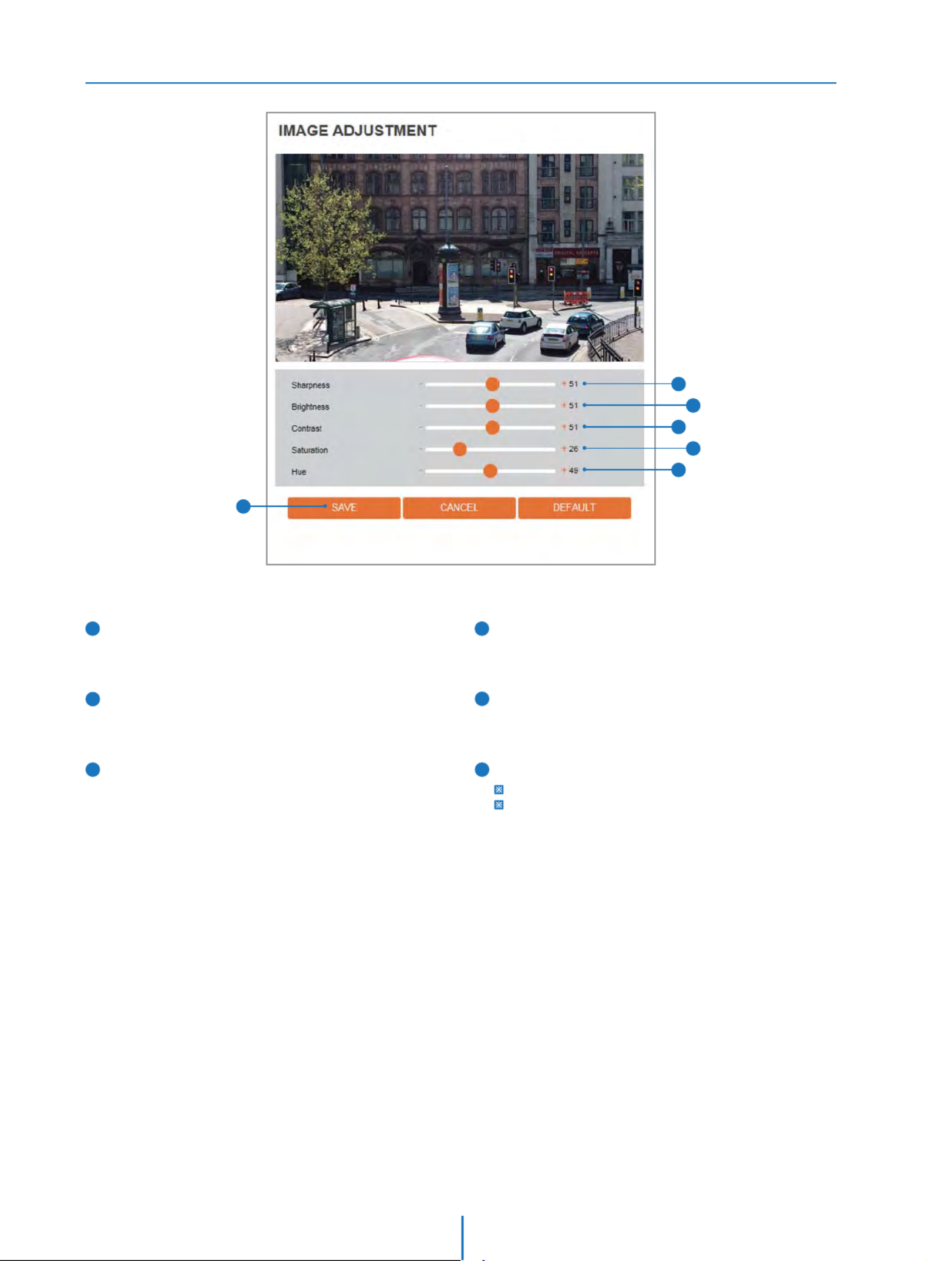
Camera Image Adjustment
Setup - Camera Setup
2
1
4
3
5
6
Sharpness
Using this control, sharpness of image can be adjusted
to meet your preference.
1
2Brightness
Using this control, brightness of image can be adjusted
to meet your preference.
3Contrast
Using this control, contrast of image can be adjusted to
meet your preference.
Saturation
Using this control, Saturation of image can be adjusted
to meet your preference.
4
5Hue
Using this control, Hue of image can be adjusted
to meet your preference.
Click 'Cancel' to return to the previous setting.
Click 'Default' to settings to the factory defaults.
6Click ‘Save’ to save the current settings.

Camera Exposure Settings
Setup - Camera Setup
7
1
2
Auto Exposure
Automatic exposure(AE) automatically sets the aperture or
shutter speed, based on the external lighting conditions
for the photo.
Exposure Level
If this value is increases, the image becomes brighter.
3AE metering
AE metering mode refers to the way in which a camera
determines the exposure.
6Gain Limit
The smaller number makes the daker image.
5Slow Shutter
Slow shutter Level lets you adjust the amount of light striking
the sensor, and essentially determines when the video sensor
sends out its batch of data for processing.
4Shutter Speed
If this speed is faster, the moving object can be photographed
without the ghost eect. However, picture can be dark if
there is no sucient lighting.
Click 'Cancel' to return to the previous setting.
Click 'Default' to settings to the factory defaults.
7Click ‘Save’ to save the current settings.
1
2
7
3
4
5
6
I'
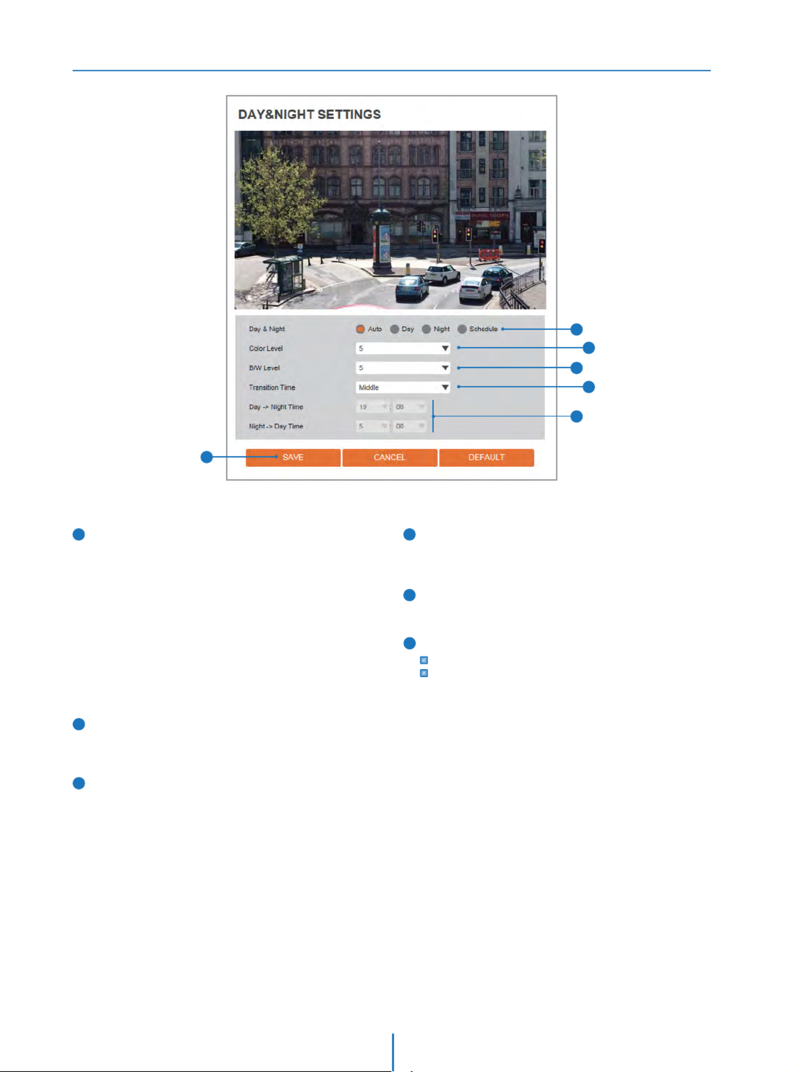
Camera Day & Night Settings
Setup - Camera Setup
2
1
4
3
5
6
Click 'Cancel' to return to the previous setting.
Click 'Default' to settings to the factory defaults.
Day & Night
Auto:
In this mode, the IR cut filter is removed automatically
depending on the light condition around.
Day:
In this mode, the IR cut filter is applied to the image
sensor all the time. Thus, the sensitivity will be reduced in
the dark light condition but the better color reproduction
performance are obtained.
Night:
In this mode, the IR cut filter on the image sensor
is removed all the time. The sensitivity will be enhanced
in the dark light condition but the image is black and white.
Schedule:
In this mode, Day / Night mode is converted
accordance with the scheduled time.
1
2
3
Color Level
It is a level to change Night mode into Day mode when
Day & Night mode is Auto.
B / W Level
It is a level to change Day mode into Night mode when
Day & Night mode is Auto.
Transition Time
If it is set to Auto, to determine the rate at which
Day / Night is converted.
4
If it is set to schedule mode, Set the time that
Day / Night is converted.
5
6Click ‘Save’ to save the current settings.
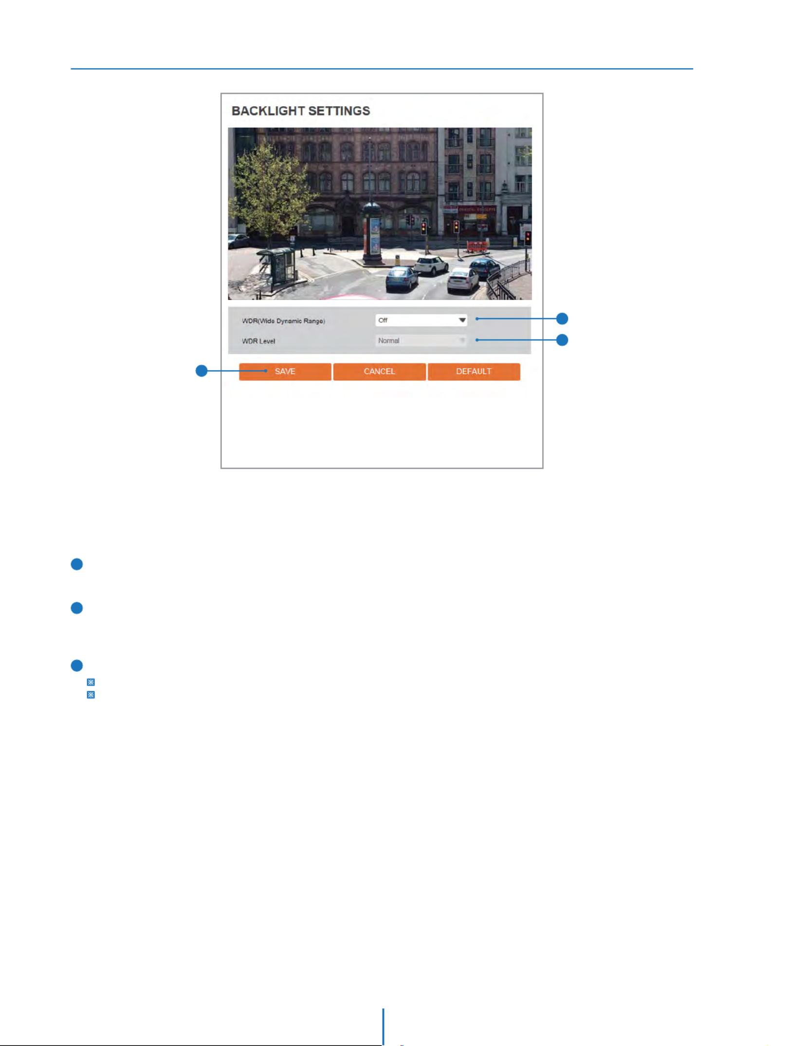
Camera Backlight Settings
Setup - Camera Setup
1
2
3
1
2
WDR (Wide Dynamic Range)
The WDR function can be enable or disable.
WDR Level
Select the WDR level depending on the difference in brightness
between the darkest and lightest part of an image.
Click 'Cancel' to return to the previous setting.
Click 'Default' to settings to the factory defaults.
3Click ‘Save’ to save the current settings.
This is a feature used for problematic light conditions where
the contrast from light to dark areas is very high.

Camera White Balance
Setup - Camera Setup
2
1
3
4
Click 'Cancel' to return to the previous setting.
Click 'Default' to settings to the factory defaults.
4Click ‘Save’ to save the current settings.
Activation
1
2White Balance Mode
Select White Balance depending on the lighting conditions.
RGB Gain
The R/G/B gain can be set only when the White Balance
Mode is set to Manual.
3
White Balance can be enable or disable.

Camera Image Enhancement
Setup - Camera Setup
2
1
3
4
Click 'Cancel' to return to the previous setting.
Click 'Default' to settings to the factory defaults.
4Click ‘Save’ to save the current settings.
3D Noise Reduction
3DNR function enables to suppress noise and retain
good video quality in low light conditions.
1
2Mirror
Reverse the video from side to side.
Flip
Reverse the video from up to down.
3

Video Enhancement
Setup - Camera Setup
1
2
Click 'Cancel' to return to the previous setting.
Click 'Default' to settings to the factory defaults.
Click ‘Save’ to save the current settings.
Flicker
This function Enable to enhance the icker situation.
1
2
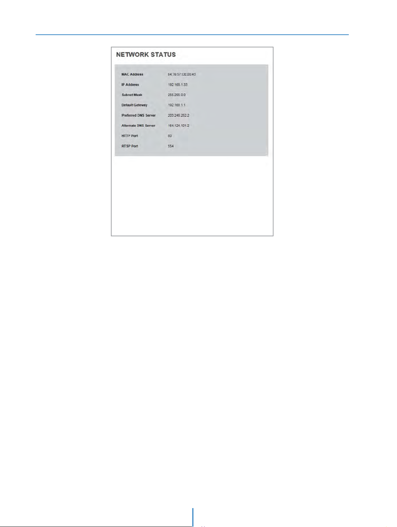
Network Status
Setup - Network Setup
This menu will show you all the information of Network setting in the camera. However, you cannot change those here.

Network Settings
Setup - Network Setup
1
3
2
5
4
6
7
8
9
10
1Network Type
Dene network IP address type from the Static Mode for the
xed IP or the Dynamic Mode by the dynamic IP address.
If you select the Static Mode, you must ll out IP Address,
Subnet Mask, Gateway, DNS Server and all ports.
If you select the Dynamic Mode, the IP address will be
allocated automatically by DHCP equipment. If you click
the Apply button to update changes, the system will be
re-booted. In this case, you have to reconnect the camera
using new IP address.
2IP Address
Dene the IP address. The address is consisted of four
numbers separated by dots and the range of each number
is from 0 to 255.
3Subnet Mask
Dene the Subnet Mask. Format is same as the IP address.
4Default Gateway
Default the Gateway IP Address. Format is same as the IP
address.
5Preferred DNS Server
Dene the DNS server IP address. Format is same as the
IP address.
6Alternate DNS Server
Dene the Secondary DNS server IP address. Format is
same as the IP address.
7HTTP Port
The HTTP port can be set to 80 which default or in between
1025 to 60000.
8HTTPS Port
The HTTPS port can be set to 443 which default or in betwe
-en1025 to 60000.
9RTSP Port
The RTSP port can be set to 554 which default or in between
1025 to 60000.
If the network type is dynamic, the IP address is changed in
below cases. Therefore, the IP address needs to be searched
again, and the camera needs to be reconnected in these
cases.
Click ‘Apply’ to make above setting eective.
- When the camera power is on / o.
- After Firmware update, Default set and reboot.
10

Auto IP Settings
Setup - Network Setup
1
2
3
Click ‘Apply’ to make above setting effective.
General Setting
Auto IP Settings function can be enable or disable.
1
Auto IP Settings Information
2
3
It displays the unique id or Auto IP address.
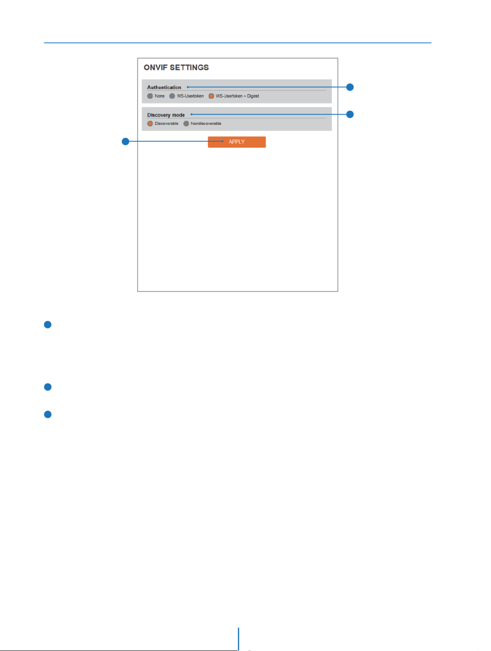
ONVIF Settings
Setup - Network Setup
1
2
3
1Authentication
None: Allows to access without ONVIF authentication.
WS - Usertoken: Allows to access with WS-User
Token of ONVIF authentication.
WS - Usertoken + Digest: Allows to access with WS-User
Token and Digest of ONVIF authentication.
2Discovery Mode
The discorvery function can be enable or disable.
3Click ‘Apply’ to make above setting effective.

UPNP Settings
Setup - Network Setup
1
2
3
1General Setting
UPNP function can be enable or disable.
2Friendly Name
Define the friendly name.
3Click ‘Apply’ to make above setting effective.

DDNS Settings
Setup - Network Setup
1
2
3
DDNS Disable
If it is selected, DDNS service does not work.
Public DDNS
To use public DDNS service, select a site address listed in the
list. After lling out the Host Name of the site, the setup is
completed by entering User Name and Password registered
in that DDNS site.
1
2
DDNS Provider Site Address
DynDNS
No-IP
www.dyndns.com
www.no-ip.com
If you setup DDNS properly, the IP address of your camera will be
updated automatically whenever IP address is changed or system
is rebooted.
If IP updating to DDNS site is failed, camera will keep retrying in
1min. interval.
Click ‘Apply’ to make above setting eective.
3

FTP Settings
Setup - Network Setup
1
2
4
6
3
5
7
FTP Server Address
Dene FTP Server IP Address. If IP Address form is incorrect,
a Message box will be shown to try again.
FTP Upload Path
Dene a path in FTP server to store video. For the path name,
English Alphabets, numbers and special characters ( / ~ !@ $
^ ( ) _ - { } [ ] ; , ) can be used.
2
General Setting
FTP function can be enable or disable.
1
3
FTP Port
Dene the FTP Server Port. If Port is not appropriate, it is
impossible to access to FTP Server.
4
To transfer / save the image to the relevant sites through FTP,
then FTP needs to be setup.
User ID
Dene User ID to access to the FTP Server. Fill out the correct
User ID registered in the FTP Server.
5
Password
Dene Password to access to the FTP Server. Fill out the
correct Password registered in the FTP Server.
6
7Click ‘Apply’ to make above setting eective.
Refer the above screen image for the example.
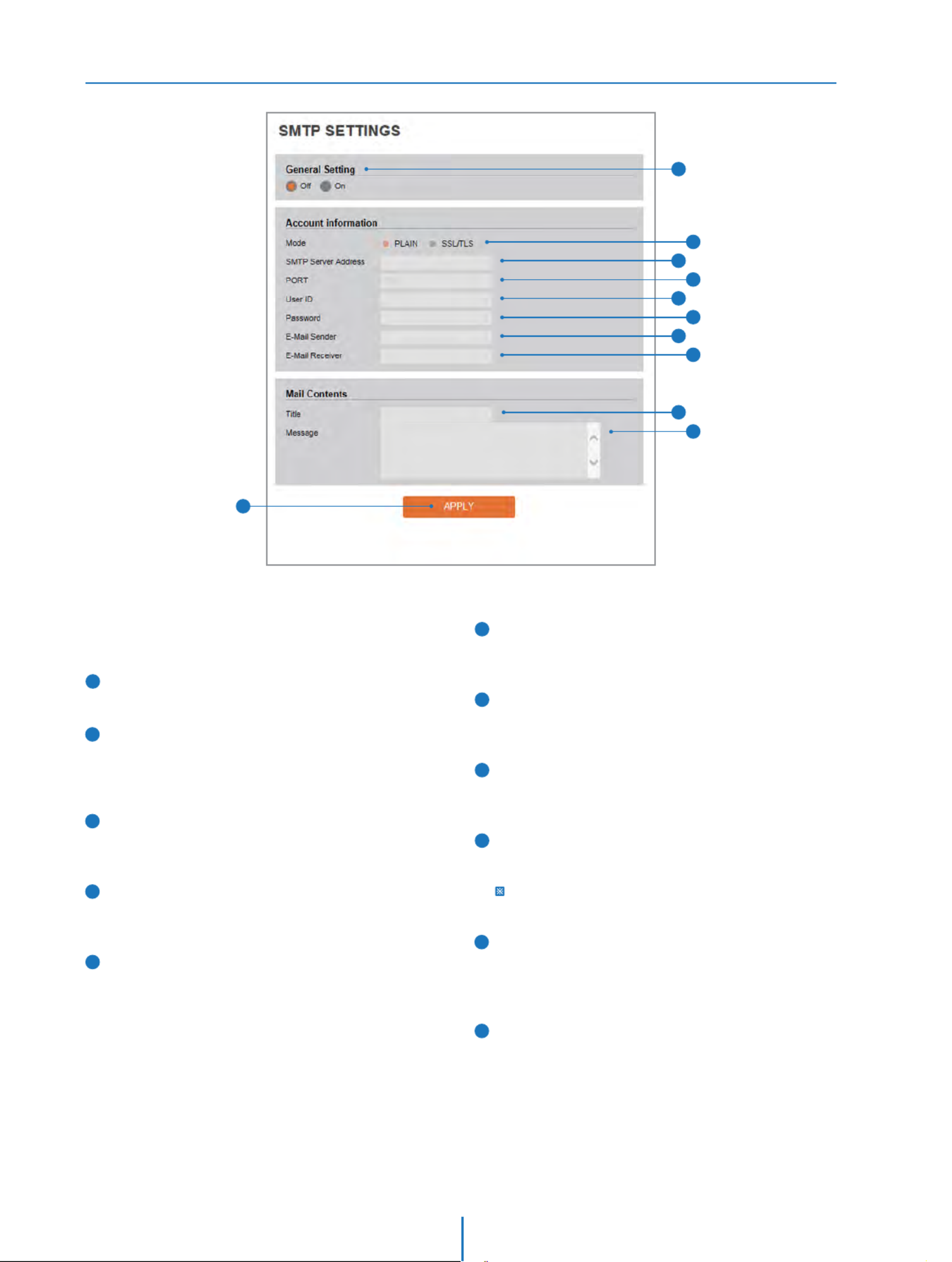
SMTP Settings
Setup - Network Setup
1
2
4
6
8
10
3
5
7
9
11
Mode
Select Security mode of SMTP from Plain or AfterSSL / TLS.
checking account setup of your SMTP Server, you may
select one.
SMTP Server Address
Dene the SMTP Server Address. If the IP Address form is
incorrect, a Message box will be shown to try again.
2
General Setting
SMTP function can be enable or disable.
1
3
Port
Dene the Port used in the Plain or security modeSSL / TLS
in the above.
4
To send / save the image to the relevant sites by Email, SMTP
needs to be setup.
User ID
Dene the User ID to access to SMTP Server. Fill out the
correct User ID registered in the SMTP Server.
5
Password
Dene the Password to access to SMTP Server. Fill out the
correct Password registered in the SMTP Server.
6
11 Click ‘Apply’ to make above setting eective.
E-Mail Sender
Dene the e-mail address of E-Mail Sender. It will be
displayed as the sender when the camera sends an E-mail.
7
E-Mail Receiver
Dene the e-mail address of E-Mail Receiver. It will be
displayed as the Receiver when the camera sends an E-mail.
8
Message
Dene the contents of E-Mail when camera sends an E-mail.
The message of the Email is limited to 40 characters including
the spaces.
10
Title
Dene the title of the E-Mail when the camera sends an
E-mail.
9
The title of the Email is limited to 40 characters including
the spaces.
Specyfikacje produktu
| Marka: | Digital Watchdog |
| Kategoria: | Kamera monitorująca |
| Model: | MegaPix DWC-MV74Wi28 |
Potrzebujesz pomocy?
Jeśli potrzebujesz pomocy z Digital Watchdog MegaPix DWC-MV74Wi28, zadaj pytanie poniżej, a inni użytkownicy Ci odpowiedzą
Instrukcje Kamera monitorująca Digital Watchdog

11 Stycznia 2025
1 Października 2024
1 Października 2024
1 Października 2024
1 Października 2024
1 Października 2024
1 Października 2024
Digital Watchdog Star-Light Plus DWC-B6563WTIR650 Instrukcja
1 Października 2024
1 Października 2024
1 Października 2024
Instrukcje Kamera monitorująca
- Kamera monitorująca Sony
- Kamera monitorująca Samsung
- Kamera monitorująca Tenda
- Kamera monitorująca Motorola
- Kamera monitorująca Stabo
- Kamera monitorująca Logitech
- Kamera monitorująca Xiaomi
- Kamera monitorująca Braun
- Kamera monitorująca Pioneer
- Kamera monitorująca TP-Link
- Kamera monitorująca Philips
- Kamera monitorująca Bosch
- Kamera monitorująca Gigaset
- Kamera monitorująca Hikvision
- Kamera monitorująca EZVIZ
- Kamera monitorująca Conceptronic
- Kamera monitorująca Panasonic
- Kamera monitorująca Canon
- Kamera monitorująca Crestron
- Kamera monitorująca Withings
- Kamera monitorująca Asus
- Kamera monitorująca Nedis
- Kamera monitorująca AG Neovo
- Kamera monitorująca Reolink
- Kamera monitorująca Boss
- Kamera monitorująca TRENDnet
- Kamera monitorująca Marquant
- Kamera monitorująca Toshiba
- Kamera monitorująca D-Link
- Kamera monitorująca August
- Kamera monitorująca Niceboy
- Kamera monitorująca Ring
- Kamera monitorująca Garmin
- Kamera monitorująca Imou
- Kamera monitorująca Blaupunkt
- Kamera monitorująca Grundig
- Kamera monitorująca APC
- Kamera monitorująca Honeywell
- Kamera monitorująca BLOW
- Kamera monitorująca Manhattan
- Kamera monitorująca Strong
- Kamera monitorująca Swann
- Kamera monitorująca Kwikset
- Kamera monitorująca Kodak
- Kamera monitorująca Cisco
- Kamera monitorująca ORNO
- Kamera monitorująca Broan
- Kamera monitorująca Moxa
- Kamera monitorująca Synology
- Kamera monitorująca Gembird
- Kamera monitorująca ZTE
- Kamera monitorująca Turing
- Kamera monitorująca Lindy
- Kamera monitorująca Minox
- Kamera monitorująca Zebra
- Kamera monitorująca DSC
- Kamera monitorująca JVC
- Kamera monitorująca ZyXEL
- Kamera monitorująca Trust
- Kamera monitorująca LogiLink
- Kamera monitorująca Furrion
- Kamera monitorująca Linksys
- Kamera monitorująca Google
- Kamera monitorująca Digitus
- Kamera monitorująca Vimar
- Kamera monitorująca V-TAC
- Kamera monitorująca Dahua Technology
- Kamera monitorująca Schneider
- Kamera monitorująca Eufy
- Kamera monitorująca Ricoh
- Kamera monitorująca Emos
- Kamera monitorująca AVMATRIX
- Kamera monitorująca Renkforce
- Kamera monitorująca Rollei
- Kamera monitorująca Marshall
- Kamera monitorująca Perel
- Kamera monitorująca Somfy
- Kamera monitorująca Uniden
- Kamera monitorująca Netgear
- Kamera monitorująca Thomson
- Kamera monitorująca DiO
- Kamera monitorująca Velleman
- Kamera monitorująca Ferguson
- Kamera monitorująca DataVideo
- Kamera monitorująca Delta Dore
- Kamera monitorująca Pyle
- Kamera monitorująca Intellinet
- Kamera monitorująca CRUX
- Kamera monitorująca Setti+
- Kamera monitorująca Waeco
- Kamera monitorująca Vivotek
- Kamera monitorująca Vtech
- Kamera monitorująca Speco Technologies
- Kamera monitorująca EtiamPro
- Kamera monitorująca Edimax
- Kamera monitorująca Petcube
- Kamera monitorująca ION
- Kamera monitorująca First Alert
- Kamera monitorująca AirLive
- Kamera monitorująca Maginon
- Kamera monitorująca EnGenius
- Kamera monitorująca SPC
- Kamera monitorująca Planet
- Kamera monitorująca Brilliant
- Kamera monitorująca Genie
- Kamera monitorująca LevelOne
- Kamera monitorująca Axis
- Kamera monitorująca Sanyo
- Kamera monitorująca Lorex
- Kamera monitorująca Control4
- Kamera monitorująca Milesight
- Kamera monitorująca Aluratek
- Kamera monitorująca Abus
- Kamera monitorująca Elro
- Kamera monitorująca Olympia
- Kamera monitorująca Hama
- Kamera monitorująca Marmitek
- Kamera monitorująca Ubiquiti Networks
- Kamera monitorująca Western Digital
- Kamera monitorująca Netatmo
- Kamera monitorująca Schwaiger
- Kamera monitorująca Promise Technology
- Kamera monitorująca GVI Security
- Kamera monitorująca AVer
- Kamera monitorująca ZKTeco
- Kamera monitorująca Netis
- Kamera monitorująca Extech
- Kamera monitorująca Denver
- Kamera monitorująca Anker
- Kamera monitorująca Allnet
- Kamera monitorująca Marshall Electronics
- Kamera monitorująca Orion
- Kamera monitorująca Yale
- Kamera monitorująca SereneLife
- Kamera monitorująca Ernitec
- Kamera monitorująca AVerMedia
- Kamera monitorująca MEE Audio
- Kamera monitorująca Genius
- Kamera monitorująca Trevi
- Kamera monitorująca Technaxx
- Kamera monitorująca Atlona
- Kamera monitorująca Hanwha
- Kamera monitorująca Overmax
- Kamera monitorująca Quantum
- Kamera monitorująca Y-cam
- Kamera monitorująca Grandstream
- Kamera monitorująca Raymarine
- Kamera monitorująca Powerfix
- Kamera monitorująca Avanti
- Kamera monitorująca Ikan
- Kamera monitorująca Alecto
- Kamera monitorująca Avidsen
- Kamera monitorująca JUNG
- Kamera monitorująca Burg Wächter
- Kamera monitorująca Foscam
- Kamera monitorująca Lumens
- Kamera monitorująca Monacor
- Kamera monitorująca Dörr
- Kamera monitorująca M-e
- Kamera monitorująca EVE
- Kamera monitorująca Smartwares
- Kamera monitorująca Adj
- Kamera monitorująca Qian
- Kamera monitorująca Arenti
- Kamera monitorująca Elmo
- Kamera monitorująca Vitek
- Kamera monitorująca Alfatron
- Kamera monitorująca UniView
- Kamera monitorująca Clas Ohlson
- Kamera monitorująca Laserliner
- Kamera monitorująca Megasat
- Kamera monitorująca REVO
- Kamera monitorująca BZBGear
- Kamera monitorująca BirdDog
- Kamera monitorująca KJB Security Products
- Kamera monitorująca HiLook
- Kamera monitorująca Profile
- Kamera monitorująca Aldi
- Kamera monitorująca Aritech
- Kamera monitorująca Acti
- Kamera monitorująca ACME
- Kamera monitorująca Flamingo
- Kamera monitorująca Caliber
- Kamera monitorująca Eminent
- Kamera monitorująca Sitecom
- Kamera monitorująca Exibel
- Kamera monitorująca Fortinet
- Kamera monitorująca KlikaanKlikuit
- Kamera monitorująca Trebs
- Kamera monitorująca Ednet
- Kamera monitorująca Steren
- Kamera monitorująca Flir
- Kamera monitorująca Buffalo
- Kamera monitorująca Arlo
- Kamera monitorująca Nest
- Kamera monitorująca Siedle
- Kamera monitorująca Hive
- Kamera monitorująca Switel
- Kamera monitorująca Chacon
- Kamera monitorująca InFocus
- Kamera monitorująca Hombli
- Kamera monitorująca Naxa
- Kamera monitorująca Konig
- Kamera monitorująca Valueline
- Kamera monitorująca BRK
- Kamera monitorująca QSC
- Kamera monitorująca Xavax
- Kamera monitorująca Vaddio
- Kamera monitorująca Gira
- Kamera monitorująca Interlogix
- Kamera monitorująca Boyo
- Kamera monitorująca IC Intracom
- Kamera monitorująca Iget
- Kamera monitorująca EverFocus
- Kamera monitorująca Adesso
- Kamera monitorująca Satel
- Kamera monitorująca POSline
- Kamera monitorująca Notifier
- Kamera monitorująca Hawking Technologies
- Kamera monitorująca Friedland
- Kamera monitorująca Nexxt
- Kamera monitorująca Monoprice
- Kamera monitorująca Watec
- Kamera monitorująca Beafon
- Kamera monitorująca Chuango
- Kamera monitorująca ETiger
- Kamera monitorująca Videcon
- Kamera monitorująca INSTAR
- Kamera monitorująca Provision ISR
- Kamera monitorująca Aqara
- Kamera monitorująca Advantech
- Kamera monitorująca Ganz
- Kamera monitorująca AViPAS
- Kamera monitorująca ClearOne
- Kamera monitorująca Ebode
- Kamera monitorująca Oplink
- Kamera monitorująca Sonic Alert
- Kamera monitorująca Linear PRO Access
- Kamera monitorująca Summer Infant
- Kamera monitorująca SMC
- Kamera monitorująca Topica
- Kamera monitorująca Kogan
- Kamera monitorująca Iiquu
- Kamera monitorująca Verint
- Kamera monitorująca Brinno
- Kamera monitorująca Rostra
- Kamera monitorująca Caddx
- Kamera monitorująca Spyclops
- Kamera monitorująca EKO
- Kamera monitorująca Kguard
- Kamera monitorująca Woonveilig
- Kamera monitorująca Mobi
- Kamera monitorująca Surveon
- Kamera monitorująca Hollyland
- Kamera monitorująca Epcom
- Kamera monitorująca Indexa
- Kamera monitorująca Lutec
- Kamera monitorująca Whistler
- Kamera monitorująca ClearView
- Kamera monitorująca VideoComm
- Kamera monitorująca IMILAB
- Kamera monitorująca 3xLOGIC
- Kamera monitorująca Pelco
- Kamera monitorująca Leviton
- Kamera monitorująca Inkovideo
- Kamera monitorująca Pentatech
- Kamera monitorująca Weldex
- Kamera monitorująca SecurityMan
- Kamera monitorująca Canyon
- Kamera monitorująca CNB Technology
- Kamera monitorująca Tapo
- Kamera monitorująca Aigis
- Kamera monitorująca Exacq
- Kamera monitorująca Brickcom
- Kamera monitorująca Laxihub
- Kamera monitorująca Securetech
- Kamera monitorująca EFB Elektronik
- Kamera monitorująca NetMedia
- Kamera monitorująca Videotec
- Kamera monitorująca Illustra
- Kamera monitorująca Nivian
- Kamera monitorująca E-bench
- Kamera monitorująca Syscom
- Kamera monitorująca Tecno
- Kamera monitorująca Night Owl
- Kamera monitorująca Guardzilla
- Kamera monitorująca Astak
- Kamera monitorująca Blink
- Kamera monitorująca Milestone Systems
- Kamera monitorująca Zavio
- Kamera monitorująca Campark
- Kamera monitorująca IPX
- Kamera monitorująca Dedicated Micros
- Kamera monitorująca Hamlet
- Kamera monitorująca Annke
- Kamera monitorująca AVTech
- Kamera monitorująca Qoltec
- Kamera monitorująca Approx
- Kamera monitorująca Digimerge
- Kamera monitorująca Wisenet
- Kamera monitorująca Infortrend
- Kamera monitorująca Epiphan
- Kamera monitorująca Mach Power
- Kamera monitorująca Compro
- Kamera monitorująca Aida
- Kamera monitorująca Ikegami
- Kamera monitorująca Accsoon
- Kamera monitorująca Vimtag
- Kamera monitorująca Gewiss
- Kamera monitorująca Alula
- Kamera monitorująca Insteon
- Kamera monitorująca Costar
- Kamera monitorująca ALC
- Kamera monitorująca Security Labs
- Kamera monitorująca Comtrend
- Kamera monitorująca Seneca
- Kamera monitorująca Avigilon
- Kamera monitorująca American Dynamics
- Kamera monitorująca Vosker
- Kamera monitorująca Sentry360
- Kamera monitorująca Bea-fon
- Kamera monitorująca Owltron
- Kamera monitorująca Enabot
- Kamera monitorująca Luis Energy
- Kamera monitorująca Sir Gawain
- Kamera monitorująca VisorTech
- Kamera monitorująca Atlantis Land
- Kamera monitorująca B & S Technology
- Kamera monitorująca I3International
- Kamera monitorująca IDIS
- Kamera monitorująca Ecobee
- Kamera monitorująca Conbrov
- Kamera monitorująca HuddleCamHD
- Kamera monitorująca Mobotix
- Kamera monitorująca IOIO
- Kamera monitorująca BIRDFY
- Kamera monitorująca I-PRO
- Kamera monitorująca DVDO
- Kamera monitorująca TCP
- Kamera monitorująca Bolin Technology
- Kamera monitorująca Nextech
Najnowsze instrukcje dla Kamera monitorująca
28 Stycznia 2025
25 Stycznia 2025
17 Stycznia 2025
17 Stycznia 2025
15 Stycznia 2025

13 Stycznia 2025

13 Stycznia 2025
13 Stycznia 2025

12 Stycznia 2025
12 Stycznia 2025