Instrukcja obsługi Dell XPS 3847
Przeczytaj poniżej 📖 instrukcję obsługi w języku polskim dla Dell XPS 3847 (55 stron) w kategorii Pulpit. Ta instrukcja była pomocna dla 7 osób i została oceniona przez 2 użytkowników na średnio 4.5 gwiazdek
Strona 1/55

Inspiron 3847
Owner’s Manual
Computer model: Inspiron 3847
Regulatory model: D16M
Regulatory type: D16M001

Notes, Cautions, and Warnings
NOTE: A NOTE indicates important information that helps you make better
use of your computer.
CAUTION: A CAUTION indicates potential damage to hardware or loss of
data if instructions are not followed.
WARNING: A WARNING indicates a potential for property damage,
personal injury, or death.
____________________
© 2013 Dell Inc.
Trademarks used in this text: Dell™, the DELL logo, and Inspiron™ are trademarks of Dell Inc.
2013 - 11 Rev. A00

Contents | 3
Contents
Before You Begin . . . . . . . . . . . . . . . . . . . . . . . . . . . 7
Safety Instructions. . . . . . . . . . . . . . . . . . . . . . . . . . 7
Recommended Tools. . . . . . . . . . . . . . . . . . . . . . . . 8
After Working Inside Your Computer . . . . . . . . . . . 9
Technical Overview . . . . . . . . . . . . . . . . . . . . . . . . 10
Inside View of Your Computer. . . . . . . . . . . . . . . . . 10
System-Board Components . . . . . . . . . . . . . . . . . . 11
Removing the Computer Cover . . . . . . . . . . . . . . 12
Procedure . . . . . . . . . . . . . . . . . . . . . . . . . . . . . . 12
Replacing the Computer Cover . . . . . . . . . . . . . . 13
Procedure . . . . . . . . . . . . . . . . . . . . . . . . . . . . . . 13
Postrequisites . . . . . . . . . . . . . . . . . . . . . . . . . . . . 13
Removing the Memory Module(s). . . . . . . . . . . . . 14
Prerequisites. . . . . . . . . . . . . . . . . . . . . . . . . . . . . 14
Procedure . . . . . . . . . . . . . . . . . . . . . . . . . . . . . . 14
Replacing the Memory Module(s). . . . . . . . . . . . . 15
Procedure . . . . . . . . . . . . . . . . . . . . . . . . . . . . . . 15
Postrequisites . . . . . . . . . . . . . . . . . . . . . . . . . . . . 15
Removing the Graphics Card . . . . . . . . . . . . . . . . 16
Prerequisites. . . . . . . . . . . . . . . . . . . . . . . . . . . . . 16
Procedure . . . . . . . . . . . . . . . . . . . . . . . . . . . . . . 16
Replacing the Graphics Card . . . . . . . . . . . . . . . . 18
Procedure . . . . . . . . . . . . . . . . . . . . . . . . . . . . . . 18
Postrequisites . . . . . . . . . . . . . . . . . . . . . . . . . . . . 18
Removing the Front Bezel . . . . . . . . . . . . . . . . . . . 19
Prerequisites. . . . . . . . . . . . . . . . . . . . . . . . . . . . . 19
Procedure . . . . . . . . . . . . . . . . . . . . . . . . . . . . . . 19

4 | Contents
Replacing the Front Bezel . . . . . . . . . . . . . . . . . . . 20
Procedure . . . . . . . . . . . . . . . . . . . . . . . . . . . . . . 20
Postrequisites . . . . . . . . . . . . . . . . . . . . . . . . . . . . 20
Removing the Wireless Mini-Card . . . . . . . . . . . . 21
Prerequisites. . . . . . . . . . . . . . . . . . . . . . . . . . . . . 21
Procedure . . . . . . . . . . . . . . . . . . . . . . . . . . . . . . 21
Replacing the Wireless Mini-Card . . . . . . . . . . . . 22
Procedure . . . . . . . . . . . . . . . . . . . . . . . . . . . . . . 22
Postrequisites . . . . . . . . . . . . . . . . . . . . . . . . . . . . 22
Removing the Primary Hard-Drive . . . . . . . . . . . . 23
Prerequisites. . . . . . . . . . . . . . . . . . . . . . . . . . . . . 23
Procedure . . . . . . . . . . . . . . . . . . . . . . . . . . . . . . 23
Replacing the Primary Hard-Drive . . . . . . . . . . . . 25
Procedure . . . . . . . . . . . . . . . . . . . . . . . . . . . . . . 25
Postrequisites . . . . . . . . . . . . . . . . . . . . . . . . . . . . 25
Removing the Secondary Hard-Drive. . . . . . . . . . 26
Prerequisites. . . . . . . . . . . . . . . . . . . . . . . . . . . . . 26
Procedure . . . . . . . . . . . . . . . . . . . . . . . . . . . . . . 26
Replacing the Secondary Hard-Drive. . . . . . . . . . 28
Procedure . . . . . . . . . . . . . . . . . . . . . . . . . . . . . . 28
Postrequisites . . . . . . . . . . . . . . . . . . . . . . . . . . . . 28
Removing the Optical Drive . . . . . . . . . . . . . . . . . 29
Prerequisites. . . . . . . . . . . . . . . . . . . . . . . . . . . . . 29
Procedure . . . . . . . . . . . . . . . . . . . . . . . . . . . . . . 29
Replacing the Optical Drive . . . . . . . . . . . . . . . . . 31
Procedure . . . . . . . . . . . . . . . . . . . . . . . . . . . . . . 31
Postrequisites . . . . . . . . . . . . . . . . . . . . . . . . . . . . 31
Removing the Front I/O Panel . . . . . . . . . . . . . . . 34
Prerequisites. . . . . . . . . . . . . . . . . . . . . . . . . . . . . 34
Procedure . . . . . . . . . . . . . . . . . . . . . . . . . . . . . . 34

Contents | 5
Replacing the Front I/O Panel. . . . . . . . . . . . . . . . 36
Procedure . . . . . . . . . . . . . . . . . . . . . . . . . . . . . . 36
Postrequisites . . . . . . . . . . . . . . . . . . . . . . . . . . . . 36
Removing the Power-Button Module . . . . . . . . . 37
Prerequisites. . . . . . . . . . . . . . . . . . . . . . . . . . . . . 37
Procedure . . . . . . . . . . . . . . . . . . . . . . . . . . . . . . 37
Replacing the Power-Button Module. . . . . . . . . . 39
Procedure . . . . . . . . . . . . . . . . . . . . . . . . . . . . . . 39
Postrequisites . . . . . . . . . . . . . . . . . . . . . . . . . . . . 39
Removing the Chassis Fan. . . . . . . . . . . . . . . . . . 40
Prerequisites. . . . . . . . . . . . . . . . . . . . . . . . . . . . . 40
Procedure . . . . . . . . . . . . . . . . . . . . . . . . . . . . . . 40
Replacing the Chassis Fan . . . . . . . . . . . . . . . . . . . 41
Procedure . . . . . . . . . . . . . . . . . . . . . . . . . . . . . . 41
Postrequisites . . . . . . . . . . . . . . . . . . . . . . . . . . . . 41
Removing the Processor Fan and
Heat Sink Assembly . . . . . . . . . . . . . . . . . . . . . . . . 42
Prerequisites. . . . . . . . . . . . . . . . . . . . . . . . . . . . . 42
Procedure . . . . . . . . . . . . . . . . . . . . . . . . . . . . . . 43
Replacing the Processor Fan and
Heat Sink Assembly . . . . . . . . . . . . . . . . . . . . . . . 44
Procedure . . . . . . . . . . . . . . . . . . . . . . . . . . . . . . 44
Postrequisites . . . . . . . . . . . . . . . . . . . . . . . . . . . . 44
Removing the Processor . . . . . . . . . . . . . . . . . . . . 45
Prerequisites. . . . . . . . . . . . . . . . . . . . . . . . . . . . . 45
Procedure . . . . . . . . . . . . . . . . . . . . . . . . . . . . . . 45
Replacing the Processor . . . . . . . . . . . . . . . . . . . . 46
Procedure . . . . . . . . . . . . . . . . . . . . . . . . . . . . . . 46
Postrequisites . . . . . . . . . . . . . . . . . . . . . . . . . . . . 47
Removing the Coin-Cell Battery. . . . . . . . . . . . . . 48
Prerequisites. . . . . . . . . . . . . . . . . . . . . . . . . . . . . 48

6 | Contents
Procedure . . . . . . . . . . . . . . . . . . . . . . . . . . . . . . 48
Replacing the Coin-Cell Battery . . . . . . . . . . . . . . 49
Procedure . . . . . . . . . . . . . . . . . . . . . . . . . . . . . . 49
Postrequisites . . . . . . . . . . . . . . . . . . . . . . . . . . . . 49
Removing the Power-Supply Unit . . . . . . . . . . . . 50
Prerequisites. . . . . . . . . . . . . . . . . . . . . . . . . . . . . 50
Procedure . . . . . . . . . . . . . . . . . . . . . . . . . . . . . . 50
Replacing the Power-Supply Unit. . . . . . . . . . . . . 51
Procedure . . . . . . . . . . . . . . . . . . . . . . . . . . . . . . 51
Postrequisites . . . . . . . . . . . . . . . . . . . . . . . . . . . . 51
Removing the System Board . . . . . . . . . . . . . . . . . 52
Prerequisites. . . . . . . . . . . . . . . . . . . . . . . . . . . . . 52
Procedure . . . . . . . . . . . . . . . . . . . . . . . . . . . . . . 53
Replacing the System Board . . . . . . . . . . . . . . . . . 54
Procedure . . . . . . . . . . . . . . . . . . . . . . . . . . . . . . 54
Postrequisites . . . . . . . . . . . . . . . . . . . . . . . . . . . . 54
Entering the Service Tag in the BIOS. . . . . . . . . . . . . 54
Flashing the BIOS . . . . . . . . . . . . . . . . . . . . . . . . . . 55
Before You Begin | 7
Before You Begin
CAUTION: To avoid losing data, save and close all open files and exit all
open programs before you turn off your computer.
1Save and close all open files and exit all open programs.
2Move your mouse pointer to the upper-right or lower-right corner of the screen to
open the Charms sidebar, and then click Settings→ Power→ Shut down.
NOTE: If you are using a different operating system, see the documentation
of your operating system for shut-down instructions.
3Disconnect your computer and all attached devices from their electrical outlets.
4Disconnect all telephone cables, network cables, and attached devices
from your computer.
5After the computer is unplugged, press and hold the power button for 5 seconds to
ground the system board.
Safety Instructions
Use the following safety guidelines to protect your computer from potential damage and
ensure your personal safety.
WARNING: Before working inside your computer, read the safety information
that shipped with your computer. For more safety best practices, see the
Regulatory Compliance home page at dell.com/regulatory_compliance.
WARNING: Disconnect all power sources before opening the computer cover or
panels. After you finish working inside the computer, replace all covers, panels,
and screws before connecting to the power source.
CAUTION: To avoid damaging the computer, make sure that the work surface is
flat and clean.
CAUTION: To avoid damaging the components and cards, handle them by their
edges and avoid touching pins and contacts.
CAUTION: Only a certified service technician is authorized to remove the
computer cover and access any of the components inside the computer. See the
safety instructions for complete information about safety precautions, working
inside your computer, and protecting against electrostatic discharge.
CAUTION: Before touching anything inside your computer, ground yourself by
touching an unpainted metal surface, such as the metal at the back of the
computer. While you work, periodically touch an unpainted metal surface to
dissipate static electricity, which could harm internal components.

8 | Before You Begin
CAUTION: When you disconnect a cable, pull on its connector or on its pull-tab,
not on the cable itself. Some cables have connectors with locking tabs or
thumb-screws that you must disengage before disconnecting the cable.
When disconnecting cables, keep them evenly aligned to avoid bending any
connector pins. When connecting cables, make sure that the connectors and
ports are correctly oriented and aligned.
CAUTION: To disconnect a network cable, first unplug the cable from your
computer and then unplug the cable from the network device.
CAUTION: Press and eject any installed card from the media-card reader.
Recommended Tools
The procedures in this document may require the following tools:
•Phillips screwdriver
•Plastic scribe

After Working Inside Your Computer | 9
After Working Inside Your Computer
CAUTION: Leaving stray or loose screws inside your computer may severely
damage your computer.
1Replace all screws and make sure that no stray screws remain
inside your computer.
2Place the computer in an upright position.
3Connect any external devices, cables, cards, and any other part(s) you removed
before working on your computer.
4Connect your computer and all attached devices to their electrical outlets.

Technical Overview | 11
System-Board Components
1 2power connector (ATX12V) processor socket
3 4processor fan connector (FNCPU1) memory module connector
(DIMM1)
5 memory module connector
(DIMM2)
6 front panel USB connector (USBF1)
7 8main power connector (ATX1) CMOS reset jumper (CMCLR1)
9 password reset jumper (PWCLR1) 10 front panel USB connector (USBF3)
11 SATA connector (SATA 3) 12 SATA connector (SATA 2)
13 power button connector (LED H1) 14 SATA connector (SATA 1)
15 SATA connector (SATA 0) 16 battery socket (BT1)
17 18front panel audio connector (AUDF1) PCI Express p11-x1 card slot (SLOT3)
19 PCI Express x16 card slot (SLOT2) 20 PCI Express p11-x1 card slot (SLOT1)
21 Mini-Card slot (MINI1) 22 chassis fan connector (FANSYS2)
1 2 4 5 7
10
13
14
1516
18
19
20
21
12
17
3
8
9
11
6
22
12 | Removing the Computer Cover
Removing the Computer Cover
WARNING: Before working inside your computer, read the safety information
that shipped with your computer and follow the steps in "Before You Begin" on
page 7. After working inside your computer, follow the instructions in "After
Working Inside Your Computer" on page 9 . For additional safety best practices
information, see the Regulatory Compliance Homepage at
dell.com/regulatory_compliance.
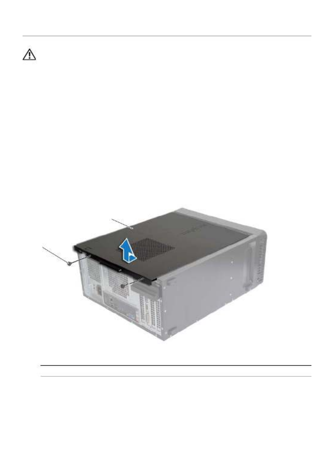
Procedure
1Place the computer on its side with the computer cover facing up.
2Using a screwdriver, remove the screws that secure the computer cover
to the chassis.
3Release the computer cover by sliding it away from the front of the computer.
4Lift the cover away from the computer and set it aside.
1 2screw computer cover
1
2

Replacing the Computer Cover | 13
Replacing the Computer Cover
WARNING: Before working inside your computer, read the safety information
that shipped with your computer and follow the steps in "Before You Begin" on
page 7. After working inside your computer, follow the instructions in "After
Working Inside Your Computer" on page 9 . For additional safety best practices
information, see the Regulatory Compliance Homepage at
dell.com/regulatory_compliance.
Procedure
1Connect all the cables and fold the cables out of the way.
2Ensure that no tools or extra parts are left inside the computer.
3Align the tabs at the bottom of the computer cover with the slots located along the
edge of the chassis.
4Press the computer cover down and slide it towards the front of the computer.
5Replace the screws that secure the computer cover to the chassis.
6Place the computer in an upright position.
Postrequisites
Follow the instructions in "After Working Inside Your Computer" on page 9.
Replacing the Memory Module(s) | 15
Replacing the Memory Module(s)
WARNING:
B
efore working inside your computer, read the safety information
that shipped with your computer and follow the steps in "Before You Begin" on
page 7. After working inside your computer, follow the instructions in
"After Working Inside Your Computer" on page 9. For more safety best practices,
see the Regulatory Compliance home page at dell.com/regulatory_compliance.
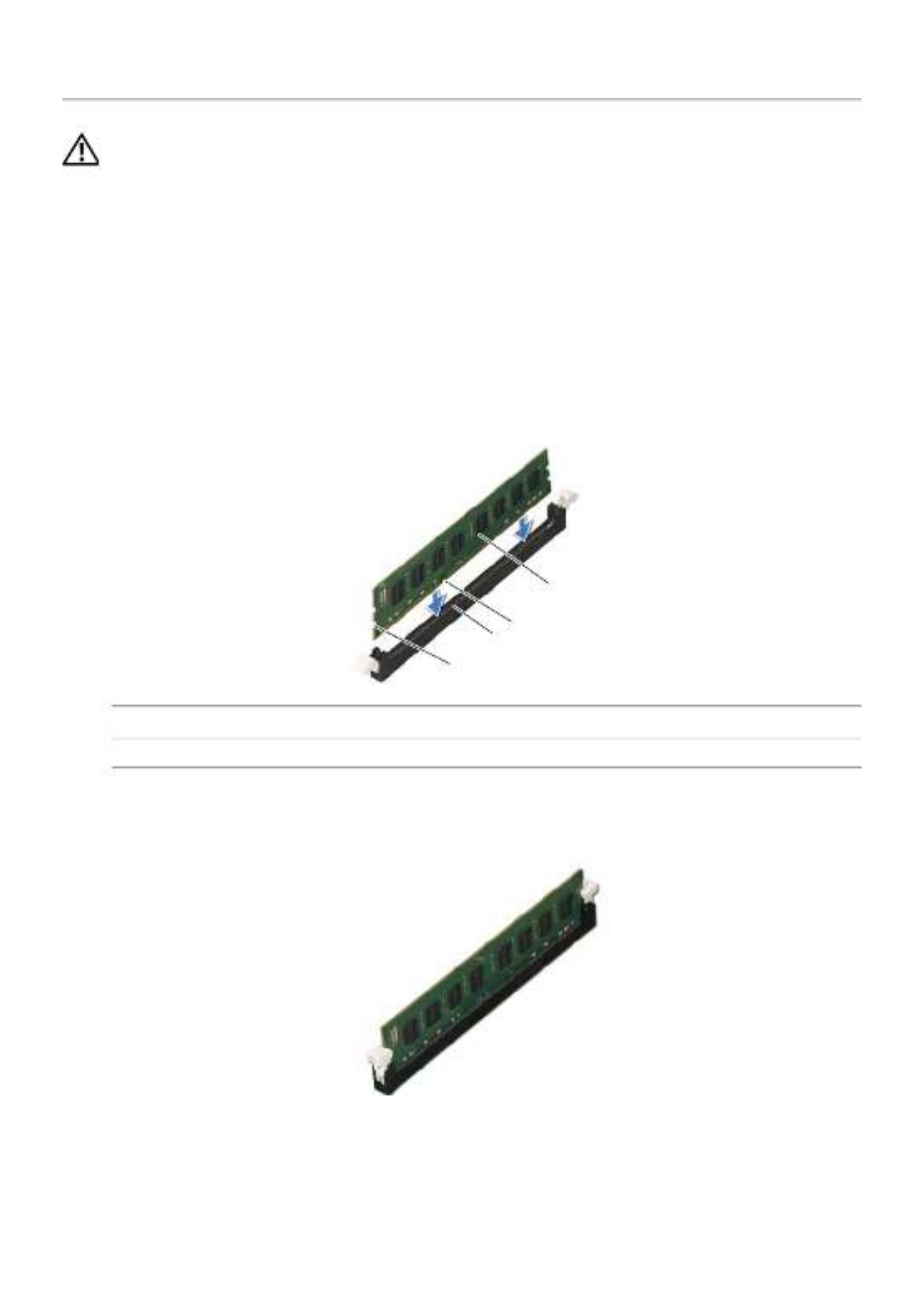
Procedure
1Press out the securing clip at each end of the memory-module connector.
2Align the notch on the memory module with the tab on the memory-module
connector.
3Insert the memory module into the memory-module connector, and press the
memory module down until it snaps into position and the securing clips lock in place.
Postrequisites
Replace the computer cover. See "Replacing the Computer Cover" on page 13.
1 2cutouts (2) tab
3 4notch memory module
23
1
4

16 | Removing the Graphics Card
Removing the Graphics Card
WARNING:
B
efore working inside your computer, read the safety information
that shipped with your computer and follow the steps in "Before You Begin" on
page 7. After working inside your computer, follow the instructions in
"After Working Inside Your Computer" on page 9. For more safety best practices,
see the Regulatory Compliance home page at dell.com/regulatory_compliance.
Prerequisites
Remove the computer cover. See "Removing the Computer Cover" on page 12.
Procedure
1Push the release tab to release the card retention bracket from the chassis.
2Push the securing tab down to release the graphics card.
3Grasp the card by its top corners, and then ease it out of the connector.
1 2card retention bracket release tab
1
2

Removing the Graphics Card | 17
1 2securing tab graphics card
1
2

18 | Replacing the Graphics Card
Replacing the Graphics Card
WARNING:
B
efore working inside your computer, read the safety information
that shipped with your computer and follow the steps in "Before You Begin" on
page 7. After working inside your computer, follow the instructions in
"After Working Inside Your Computer" on page 9. For more safety best practices,
see the Regulatory Compliance home page at dell.com/regulatory_compliance.
Procedure
1Locate the PCI-Express x16 card slot. See "System-Board Components" on page .11
2Align the graphics card with the PCI-Express x16 card slot on the system board.
3Place the card in the slot and press down firmly. Ensure that the card is firmly
seated in the slot.
4Rotate the card retention bracket towards the computer until it snaps into place.
Postrequisites
Replace the computer cover. See "Replacing the Computer Cover" on page 13.

20 | Replacing the Front Bezel
Replacing the Front Bezel
WARNING:
B
efore working inside your computer, read the safety information
that shipped with your computer and follow the steps in "Before You Begin" on
page 7. After working inside your computer, follow the instructions in
"After Working Inside Your Computer" on page 9. For more safety best practices,
see the Regulatory Compliance home page at dell.com/regulatory_compliance.
Procedure
1Align and insert the front bezel clamps into the front panel slots.
2Rotate the front bezel towards the computer until the front bezel tabs snap into
place.
Postrequisites
Replace the computer cover. See "Replacing the Computer Cover" on page 13.

Removing the Wireless Mini-Card | 21
Removing the Wireless Mini-Card
WARNING: Before working inside your computer, read the safety information
that shipped with your computer and follow the steps in "Before You Begin" on
page 7. After working inside your computer, follow the instructions in "After
Working Inside Your Computer" on page 9 . For additional safety best practices,
see the Regulatory Compliance home page at dell.com/regulatory_compliance.
Prerequisites
Remove the computer cover. See "Removing the Computer Cover" on page 12.
Procedure
1Locate the mini-card slot (MINI1) on the system board. See "System-Board
Components" on page .11
2Disconnect the antenna cables from the wireless mini-card.
3Remove the screw that secures the wireless mini-card to the system board.
4Slide and remove the wireless mini-card from the mini-card connector.
1 2screw antenna cables (2)
3 4wireless mini-card mini-card slot (MINI1)
2
1
3
4

22 | Replacing the Wireless Mini-Card
Replacing the Wireless Mini-Card
WARNING: Before working inside your computer, read the safety information
that shipped with your computer and follow the steps in "Before You Begin" on
page 7. After working inside your computer, follow the instructions in "After
Working Inside Your Computer" on page 9 . For more safety best practices,
see the Regulatory Compliance home page at dell.com/regulatory_compliance.
Procedure
CAUTION: To avoid damage to the wireless mini-card, do not place any cables
under it.
1Align the notch on the wireless mini-card with the tab on the mini-card connector.
2Slide the wireless mini-card at an angle into the system-board connector.
3Press the other end of the wireless mini-card down and replace the screw that
secures the wireless mini-card to the system board.
4Connect the antenna cables to the wireless mini-card.
The following table provides the antenna-cable color scheme for the wireless
mini-card supported by your computer.
Postrequisites
Replace the computer cover. See "Replacing the Computer Cover" on page 13.
Connectors on the wireless card Antenna-cable color
Main (white triangle)
Auxiliary (black triangle)
White
Black

24 | Removing the Primary Hard-Drive
4Remove the screws that secure the hard-drive brackets to the primary hard-drive.
5Lift the primary hard-drive off the hard-drive brackets.
1 2screws (2) hard-drive brackets (2)
3 primary hard-drive
23
1

Replacing the Primary Hard-Drive | 25
Replacing the Primary Hard-Drive
WARNING:
B
efore working inside your computer, read the safety information
that shipped with your computer and follow the steps in "Before You Begin" on
page 7. After working inside your computer, follow the instructions in
"After Working Inside Your Computer" on page 9. For more safety best practices,
see the Regulatory Compliance home page at dell.com/regulatory_compliance.
CAUTION: Hard drives are fragile. Exercise care when handling the hard drive.
Procedure
1Align the screw holes on the primary hard-drive with the screw holes on the
hard-drive brackets.
2Replace the screws that secure the hard-drive brackets to the primary hard-drive.
3Slide the primary hard-drive assembly into the computer.
4Replace the screws that secure the primary hard-drive assembly to the chassis.
5Connect the power and data cables to the primary hard-drive assembly.
Postrequisites
Replace the computer cover. See "Replacing the Computer Cover" on page 13.

26 | Removing the Secondary Hard-Drive
Removing the Secondary Hard-Drive
WARNING:
B
efore working inside your computer, read the safety information
that shipped with your computer and follow the steps in "Before You Begin" on
page 7. After working inside your computer, follow the instructions in
"After Working Inside Your Computer" on page 9. For more safety best practices,
see the Regulatory Compliance home page at dell.com/regulatory_compliance.
CAUTION: To avoid data loss, do not remove the hard drive while the computer is
On or in Sleep state.
CAUTION: Hard drives are fragile. Exercise care when handling the hard drive.
Prerequisites
Remove the computer cover. See "Removing the Computer Cover" on page 12.
Procedure
1Disconnect the power and data cables from the secondary hard-drive assembly.
2Remove the screws that secure the secondary hard-drive assembly to the chassis.

Removing the Secondary Hard-Drive | 27
3Slide the secondary hard-drive assembly out of the computer.
4Remove the screws that secure the hard-drive brackets to the secondary hard-
drive.
5Lift the secondary hard-drive off the hard-drive brackets.
1 2power cable data cable
3 4secondary hard-drive assembly screw
1 2screws (2) hard-drive brackets (2)
3 secondary hard-drive
1
4
2
3
23
1

28 | Replacing the Secondary Hard-Drive
Replacing the Secondary Hard-Drive
WARNING:
B
efore working inside your computer, read the safety information
that shipped with your computer and follow the steps in "Before You Begin" on
page 7. After working inside your computer, follow the instructions in
"After Working Inside Your Computer" on page 9. For more safety best practices,
see the Regulatory Compliance home page at dell.com/regulatory_compliance.
CAUTION: Hard drives are fragile. Exercise care when handling the hard drive.
Procedure
1Align the screw holes on the secondary hard-drive with the screw holes on the
hard-drive brackets.
2Replace the screws that secure the hard-drive brackets to the secondary
hard-drive.
3Slide the secondary hard-drive assembly into the computer.
4Replace the screws that secure the secondary hard-drive assembly to the chassis.
5Connect the power and data cables to the secondary hard-drive assembly.
Postrequisites
Replace the computer cover. See "Replacing the Computer Cover" on page 13.

Removing the Optical Drive | 29
Removing the Optical Drive
WARNING: Before working inside your computer, read the safety information
that shipped with your computer and follow the steps in "Before You Begin" on
page 7. After working inside your computer, follow the instructions in "After
Working Inside Your Computer" on page 9 . For additional safety best practices
information, see the Regulatory Compliance Homepage at
dell.com/regulatory_compliance.
Prerequisites
1Remove the computer cover. See "Removing the Computer Cover" on page .12
2Remove the front bezel. See "Removing the Front Bezel" on page .19
Procedure
1Disconnect the power and data cables from the optical drive.
2Remove the screws that secure the optical drive to the chassis.

Replacing the Optical Drive | 31
Replacing the Optical Drive
WARNING: Before working inside your computer, read the safety information
that shipped with your computer and follow the steps in "Before You Begin" on
page 7. After working inside your computer, follow the instructions in "After
Working Inside Your Computer" on page 9 . For additional safety best practices
information, see the Regulatory Compliance Homepage at
dell.com/regulatory_compliance.
Procedure
1Gently slide the optical drive into the optical-drive bay through the front of the
computer.
2Align the screw holes on the optical drive with the screw holes on the chassis.
3Replace the screws that secure the optical drive to the chassis.
4Connect the power and data cables to the optical drive.
NOTE: Repeat steps 1 to 4 to replace secondary optical-drive, if applicable.
Postrequisites
1Replace the front bezel. See "Replacing the Front Bezel" on page .20
2Replace the computer cover. See "Replacing the Computer Cover" on page .13

32 | Replacing the Optical Drive
Installing a Secondary Optical Drive (optional)
1To install a secondary optical-drive, pull the break-away metal plate off the chassis.
1 metal plate
1
Replacing the Optical Drive | 33
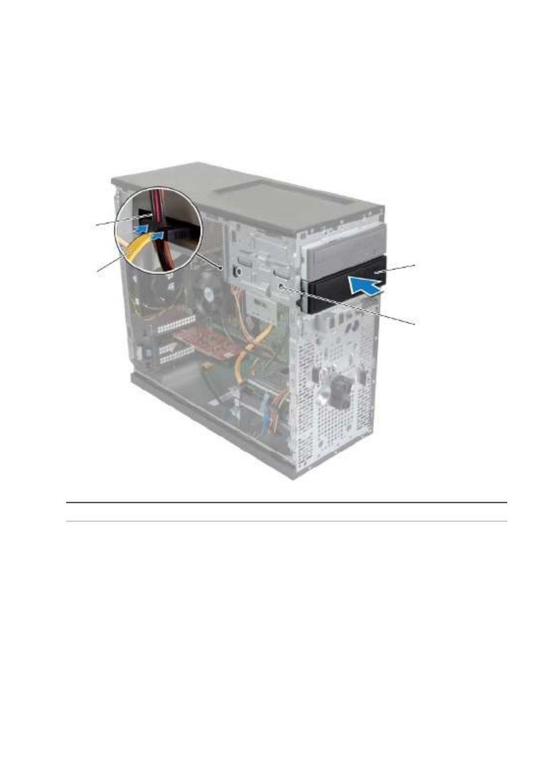
2Gently slide the secondary optical-drive into the optical drive bay through the front
of the computer.
3Align the screw holes on the secondary optical-drive with the screw holes on the
chassis.
4Replace the screws that secure the secondary optical-drive to the chassis.
5Connect the power and data cables to the secondary optical drive.
1 2secondary optical drive screws (2)
3 data cable 4 power cable
1
3
4
2

34 | Removing the Front I/O Panel
Removing the Front I/O Panel
WARNING: Before working inside your computer, read the safety information
that shipped with your computer and follow the steps in "Before You Begin" on
page 7. After working inside your computer, follow the instructions in "After
Working Inside Your Computer" on page 9 . For additional safety best practices
information, see the Regulatory Compliance Homepage at
dell.com/regulatory_compliance.
Prerequisites
1Remove the computer cover. See "Removing the Computer Cover" on page .12
2Remove the front bezel. See "Removing the Front Bezel" on page .19
Procedure
CAUTION: When sliding the front I/O panel out of the computer, be extremely
careful. Carelessness may result in damage to the cable connectors and the cable
routing clips.
NOTE: Note the routing of all cables as you remove them so that you can re-route
them correctly after you replace the front I/O panel.
1Disconnect the front I/O panel cables from the system board connectors (AUDF1,
USBF1, and USBF3). See "System-Board Components" on page .11
2Remove the screw that secures the front I/O panel to the front panel.

Removing the Front I/O Panel | 35
3Slide the front I/O panel towards the side as shown in the illustration to release the
clamps from the front panel and pull it away.
1 2front I/O panel screw
3 I/O panel cables (3)
3
1
2

36 | Replacing the Front I/O Panel
Replacing the Front I/O Panel
WARNING: Before working inside your computer, read the safety information
that shipped with your computer and follow the steps in "Before You Begin" on
page 7. After working inside your computer, follow the instructions in "After
Working Inside Your Computer" on page 9 . For additional safety best practices
information, see the Regulatory Compliance Homepage at
dell.com/regulatory_compliance.
Procedure
1Align and slide the front I/O panel clamps into the front I/O panel clamp slot.
2Replace the screw that secures the front I/O panel to the front panel.
3Connect the front I/O panel cables to the system board connectors (AUDF1, USBF1,
and USBF3). See "System-Board Components" on page .11
Postrequisites
1Replace the front bezel. See "Replacing the Front Bezel" on page .20
2Replace the computer cover. See "Replacing the Computer Cover" on page .13

Removing the Power-Button Module | 37
Removing the Power-Button Module
WARNING:
B
efore working inside your computer, read the safety information
that shipped with your computer and follow the steps in "Before You Begin" on
page 7. After working inside your computer, follow the instructions in
"After Working Inside Your Computer" on page 9. For more safety best practices,
see the Regulatory Compliance home page at dell.com/regulatory_compliance.
Prerequisites
1Remove the computer cover. See "Removing the Computer Cover" on page .12
2Remove the front bezel. See "Removing the Front Bezel" on page .19
Procedure
NOTE: Note the routing of the cable as you remove it so that you can re-route it
correctly after you replace the power-button module.
1Disconnect the power-button module cable from the system-board connector
(LEDH1). See "System-Board Components" on page .11
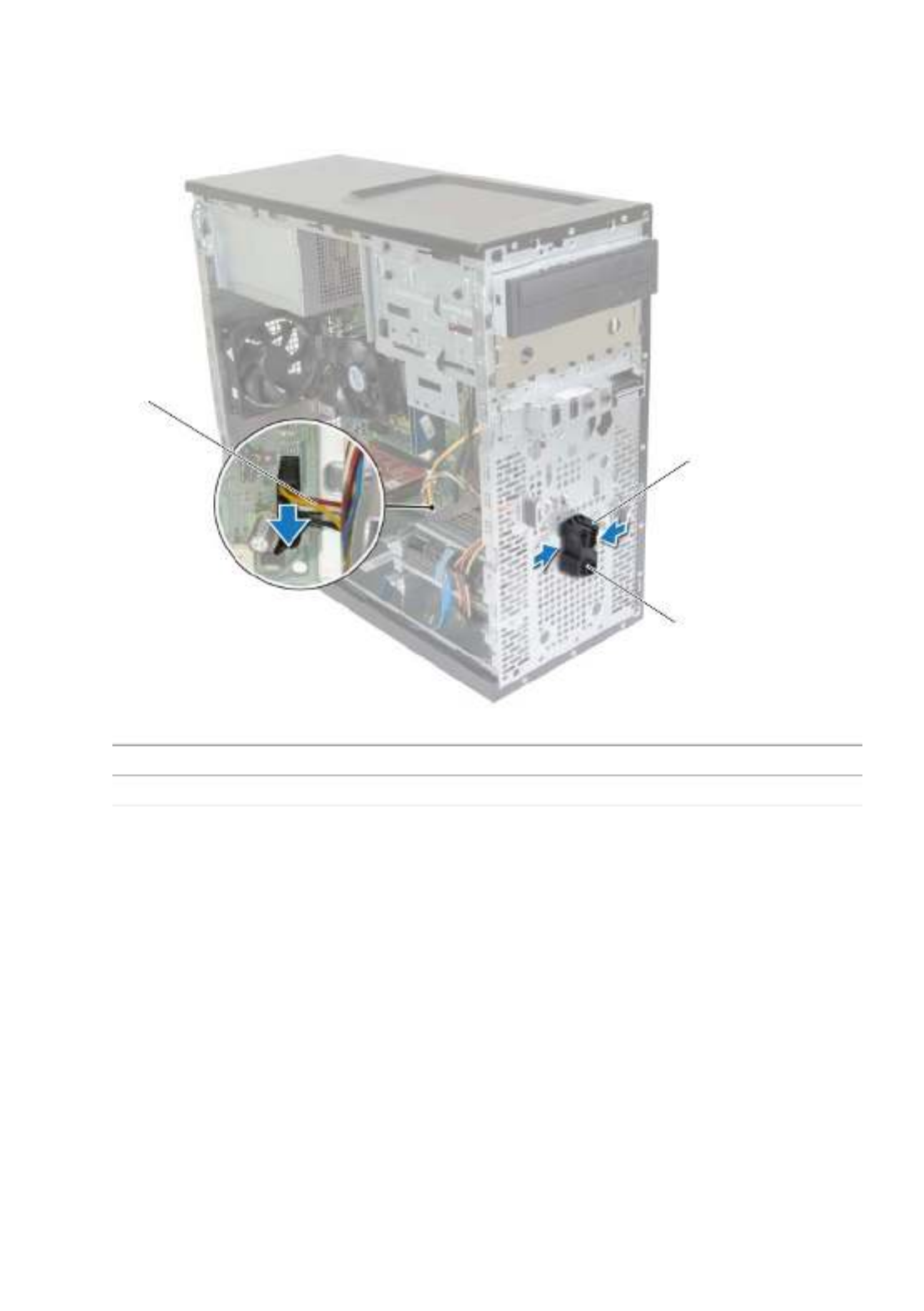
38 | Removing the Power-Button Module
2Press the tabs on the power-button module and pull the power-button module to
release it from the front panel.
3Set aside the power-button module.
1 2tabs power-button module
3 power-button cable
3
1
2

Replacing the Power-Button Module | 39
Replacing the Power-Button Module
WARNING:
B
efore working inside your computer, read the safety information
that shipped with your computer and follow the steps in "Before You Begin" on
page 7. After working inside your computer, follow the instructions in
"After Working Inside Your Computer" on page 9. For more safety best practices,
see the Regulatory Compliance home page at dell.com/regulatory_compliance.
Procedure
1Align and push the power-button module tabs into the slots on the front panel.
2Connect the power-button module cable to the system board connector (LEDH1).
See "System-Board Components" on page .11
3Route the power-button module cable through its routing guide.
Postrequisites
1Replace the front bezel. See "Replacing the Front Bezel" on page .20
2Replace the computer cover. See "Replacing the Computer Cover" on page .13

40 | Removing the Chassis Fan
Removing the Chassis Fan
WARNING:
B
efore working inside your computer, read the safety information
that shipped with your computer and follow the steps in "Before You Begin" on
page 7. After working inside your computer, follow the instructions in
"After Working Inside Your Computer" on page 9. For more safety best practices,
see the Regulatory Compliance home page at dell.com/regulatory_compliance.
Prerequisites
Remove the computer cover. See "Removing the Computer Cover" on page 12.
Procedure
1Disconnect the chassis-fan cable from the system board connector (FANSYS2). See
"System-Board Components" on page .11
2Remove the screws that secure the chassis fan to the chassis.
3Slide and lift the chassis fan away from the computer as shown in the illustration.
1 2screws (4) chassis fan
3 chassis-fan cable
2
3
1

Replacing the Chassis Fan | 41
Replacing the Chassis Fan
WARNING:
B
efore working inside your computer, read the safety information
that shipped with your computer and follow the steps in "Before You Begin" on
page 7. After working inside your computer, follow the instructions in
"After Working Inside Your Computer" on page 9. For more safety best practices,
see the Regulatory Compliance home page at dell.com/regulatory_compliance.
Procedure
1Align the screw holes on the chassis fan with the screw holes on the chassis.
2Replace the screws that secure the chassis fan to the chassis.
3Connect the chassis-fan cable to the system board connector (FANSYS2). See
"System-Board Components" on page .11
Postrequisites
1Replace the front bezel. See "Replacing the Front Bezel" on page .20
2Replace the computer cover. See "Replacing the Computer Cover" on page .13

42 | Removing the Processor Fan and Heat Sink Assembly
Removing the Processor Fan and
Heat Sink Assembly
WARNING: Before working inside your computer, read the safety information
that shipped with your computer and follow the steps in "Before You Begin" on
page 7. After working inside your computer, follow the instructions in
"After Working Inside Your Computer" on page 9. For more safety best practices,
see the Regulatory Compliance home page at dell.com/regulatory_compliance.
WARNING: The heat sink may become hot during normal operation.
Allow sufficient time for the heat sink to cool before you touch it.
CAUTION: To ensure maximum cooling for the processor, do not touch the heat
transfer areas on the heat sink. The oils in your skin can reduce the heat transfer
capability of the thermal grease.
Prerequisites
Remove the computer cover. See "Removing the Computer Cover" on page 12.

44 | Replacing the Processor Fan and Heat Sink Assembly
Replacing the Processor Fan and
Heat Sink Assembly
WARNING:
B
efore working inside your computer, read the safety information
that shipped with your computer and follow the steps in "Before You Begin" on
page 7. After working inside your computer, follow the instructions in
"After Working Inside Your Computer" on page 9. For more safety best practices,
see the Regulatory Compliance home page at dell.com/regulatory_compliance.
CAUTION: Incorrect alignment of the heat sink can cause damage to the system
board and processor.
Procedure
NOTE: The original thermal grease can be reused if the original processor and heat
sink are reinstalled together.
CAUTION: If either the processor or the heat sink is replaced, use the thermal
grease provided in the kit to make sure that thermal conductivity is achieved.
1Place the processor fan and heat-sink assembly over the processor.
2Connect the processor-fan cable to the system board connector (FNCPU1).
See "System-Board Components" on page .11
3Align the captive screws on the processor fan heat-sink assembly with the screw
holes on the system board.
4Tighten the captive screws that secure the processor fan and heat-sink assembly to
the system board.
Postrequisites
Replace the computer cover. See "Replacing the Computer Cover" on page 16.

Removing the Processor | 45
Removing the Processor
WARNING:
B
efore working inside your computer, read the safety information
that shipped with your computer and follow the steps in "Before You Begin" on
page 7. After working inside your computer, follow the instructions in
"After Working Inside Your Computer" on page 9. For more safety best practices,
see the Regulatory Compliance home page at dell.com/regulatory_compliance.
CAUTION: Processors are fragile. Handle the processor only by the edges and do
not touch the metal pins.
Prerequisites
1 Remove the computer cover. See "Removing the Computer Cover" on page .12
2 Remove the processor fan and heat sink. See "Removing the Processor Fan and
Heat Sink Assembly" on page .42
Procedure
1 Press the release-lever down and then pull it outwards to release it from the
securing tab.
2 Extend the release-lever completely to open the processor cover.
3 Gently lift the processor and remove it from the processor socket.
1 2release lever securing tab
3 4processor cover socket
5 processor
14
3
2
5

46 | Replacing the Processor
Replacing the Processor
WARNING:
B
efore working inside your computer, read the safety information
that shipped with your computer and follow the steps in "Before You Begin" on
page 7. After working inside your computer, follow the instructions in
"After Working Inside Your Computer" on page 9. For more safety best practices,
see the Regulatory Compliance home page at dell.com/regulatory_compliance.
Procedure
NOTE: A new processor ships with a thermal pad in the package. In some cases, the
processor may ship with the thermal pad attached to it.
1Ensure that the release lever on the processor socket is fully extended in the open
position.
2Align the pin-1 corner on the processor with the pin-1 corner on the processor
socket, and then place the processor in the processor socket.
NOTE: The pin-1 corner of the processor has a triangle that aligns with the
triangle on the pin-1 corner on the processor socket. When the processor is
properly seated, all four corners are aligned at the same height. If one or more
corners of the processor are higher than the others, the processor is not
seated properly.
3When the processor is fully seated in the socket, close the processor cover.
4Pivot the release-lever down and place it under the tab on the processor cover.
1 2processor pin-1 indicator processor
3 4alignment tabs (2) alignment post
5 6processor-cover notch processor cover
7 release lever
1
2
345
67

Replacing the Processor | 47
Postrequisites
1Replace the processor fan and heat sink. See "Replacing the Processor Fan and
Heat Sink Assembly" on page .44
2Replace the computer cover. See "Replacing the Computer Cover" on page 16.

48 | Removing the Coin-Cell Battery
Removing the Coin-Cell Battery
WARNING:
B
efore working inside your computer, read the safety information
that shipped with your computer and follow the steps in "Before You Begin" on
page 7. After working inside your computer, follow the instructions in
"After Working Inside Your Computer" on page 9. For more safety best practices,
see the Regulatory Compliance home page at dell.com/regulatory_compliance.
CAUTION: Removing the coin-cell battery resets the BIOS settings to default.
It is recommended that you note the BIOS settings before removing the
coin-cell battery.
Prerequisites
Remove the computer cover. See "Removing the Computer Cover" on page 12.
Procedure
1Locate the battery socket (BT1). See "System-Board Components" on page .11
2Press the battery-release lever away from the coin-cell battery until the coin-cell
battery pops up.
3Lift the coin-cell battery out of its socket.
1 2coin-cell battery securing clip
1 2
Specyfikacje produktu
| Marka: | Dell |
| Kategoria: | Pulpit |
| Model: | XPS 3847 |
Potrzebujesz pomocy?
Jeśli potrzebujesz pomocy z Dell XPS 3847, zadaj pytanie poniżej, a inni użytkownicy Ci odpowiedzą
Instrukcje Pulpit Dell

7 Października 2024
2 Października 2024
29 Września 2024
29 Września 2024
29 Września 2024
29 Września 2024
29 Września 2024
29 Września 2024
29 Września 2024
29 Września 2024
Instrukcje Pulpit
- Pulpit Sony
- Pulpit Samsung
- Pulpit LG
- Pulpit Sharp
- Pulpit Supermicro
- Pulpit Lenovo
- Pulpit Gigabyte
- Pulpit Acer
- Pulpit Fujitsu
- Pulpit LC-Power
- Pulpit Promethean
- Pulpit Mio
- Pulpit Viewsonic
- Pulpit Asus
- Pulpit Medion
- Pulpit MSI
- Pulpit Toshiba
- Pulpit Haier
- Pulpit HP
- Pulpit Tripp Lite
- Pulpit Moxa
- Pulpit ZTE
- Pulpit JYSK
- Pulpit Apple
- Pulpit AOC
- Pulpit Vtech
- Pulpit Razer
- Pulpit Kobo
- Pulpit NEC
- Pulpit Axis
- Pulpit Optoma
- Pulpit Asrock
- Pulpit Microsoft
- Pulpit Sharkoon
- Pulpit ECS
- Pulpit BenQ
- Pulpit BDI
- Pulpit Zotac
- Pulpit Alienware
- Pulpit Emachines
- Pulpit Parisot
- Pulpit Maxdata
- Pulpit Woood
- Pulpit Wehkamp
- Pulpit InFocus
- Pulpit Intel
- Pulpit Targa
- Pulpit Peaq
- Pulpit Seagate
- Pulpit Shuttle
- Pulpit Vorago
- Pulpit VXL
- Pulpit Foxconn
- Pulpit Ibm
- Pulpit Packard Bell
- Pulpit Advantech
- Pulpit Kogan
- Pulpit MP
- Pulpit Elitegroup
- Pulpit Smart Things
- Pulpit ONYX
- Pulpit System76
- Pulpit Zoostorm
- Pulpit Bestar
- Pulpit Pelco
- Pulpit Altra
- Pulpit Dell Wyse
- Pulpit AOpen
- Pulpit NComputing
- Pulpit MvixUSA
- Pulpit Faytech
- Pulpit AIS
- Pulpit Wyse
Najnowsze instrukcje dla Pulpit

15 Października 2024
15 Października 2024

14 Października 2024

12 Października 2024

10 Października 2024
9 Października 2024
9 Października 2024

9 Października 2024
8 Października 2024
8 Października 2024