Instrukcja obsługi Dell Inspiron 5521
Przeczytaj poniżej 📖 instrukcję obsługi w języku polskim dla Dell Inspiron 5521 (94 stron) w kategorii laptop. Ta instrukcja była pomocna dla 11 osób i została oceniona przez 2 użytkowników na średnio 4.5 gwiazdek
Strona 1/94

Dell Inspiron 3521/5521
Owner’s Manual
Computer model: Inspiron 3521/5521
Regulatory model: P28F
Regulatory type: P28F001

Notes, Cautions, and Warnings
NOTE: A NOTE indicates important information that helps you make better
use of your computer.
CAUTION: A CAUTION indicates potential damage to hardware or loss of
data if instructions are not followed.
WARNING: A WARNING indicates a potential for property damage,
personal injury, or death.
____________________
© 2012 Dell Inc.
Trademarks used in this text: Dell™, the DELL logo, and Inspiron
™ are trademarks of Dell Inc.;
Microsoft®, Windows®, and the Windows start button logo are either trademarks or registered
trademarks of Microsoft Corporation in the United States and/or other countries; Bluetooth
®
is a registered trademark owned by Bluetooth SIG, Inc. and is used by Dell under license.
2012 - 11 Rev. A00

Contents | 3
Contents
1 Before You Begin . . . . . . . . . . . . . . . . . . . . . . . . 7
Turn Off Your Computer and Connected Devices . . . 7
Safety Instructions . . . . . . . . . . . . . . . . . . . . . . . . 7
Recommended Tools. . . . . . . . . . . . . . . . . . . . . . 8
2 After Working Inside Your Computer. . . . . . . . 9
3 Removing the Battery . . . . . . . . . . . . . . . . . . . 11
Procedure 11 . . . . . . . . . . . . . . . . . . . . . . . . . . . .
4 Replacing the Battery . . . . . . . . . . . . . . . . . . . 13
Procedure 13 . . . . . . . . . . . . . . . . . . . . . . . . . . . .
Postrequisites . . . . . . . . . . . . . . . . . . . . . . . . . . 13
5 Removing the Memory Module(s) . . . . . . . . . 15
Prerequisites. . . . . . . . . . . . . . . . . . . . . . . . . . . 15
Procedure 15 . . . . . . . . . . . . . . . . . . . . . . . . . . . .
6 Replacing the Memory Module(s). . . . . . . . . . 17
Procedure 17 . . . . . . . . . . . . . . . . . . . . . . . . . . . .
Postrequisites . . . . . . . . . . . . . . . . . . . . . . . . . . 17
7 Removing the Optical-Drive Assembly . . . . . 19
Prerequisites. . . . . . . . . . . . . . . . . . . . . . . . . . . 19
Procedure 19 . . . . . . . . . . . . . . . . . . . . . . . . . . . .
8 Replacing the Optical-Drive Assembly . . . . . 21
Procedure . . . . . . . . . . . . . . . . . . . . . . . . . . . . 21
Postrequisites . . . . . . . . . . . . . . . . . . . . . . . . . . 21
9 Removing the Hard-Drive Assembly . . . . . . . 23
Prerequisites. . . . . . . . . . . . . . . . . . . . . . . . . . . 23
Procedure . . . . . . . . . . . . . . . . . . . . . . . . . . . . 23
10 Replacing the Hard-Drive Assembly. . . . . . . . 25
Procedure . . . . . . . . . . . . . . . . . . . . . . . . . . . . 25
Postrequisites . . . . . . . . . . . . . . . . . . . . . . . . . . 25

4 | Contents
11 Removing the Keyboard . . . . . . . . . . . . . . . . . 27
Prerequisites . . . . . . . . . . . . . . . . . . . . . . . . . . . 27
Procedure . . . . . . . . . . . . . . . . . . . . . . . . . . . . 27
12 Replacing the Keyboard . . . . . . . . . . . . . . . . . 29
Procedure . . . . . . . . . . . . . . . . . . . . . . . . . . . . 29
Postrequisites . . . . . . . . . . . . . . . . . . . . . . . . . . 29
13 Removing the Palm-Rest. . . . . . . . . . . . . . . . . 31
Prerequisites . . . . . . . . . . . . . . . . . . . . . . . . . . . 31
Procedure . . . . . . . . . . . . . . . . . . . . . . . . . . . . 31
14 Replacing the Palm-Rest . . . . . . . . . . . . . . . . . 35
Procedure . . . . . . . . . . . . . . . . . . . . . . . . . . . . 35
Postrequisites . . . . . . . . . . . . . . . . . . . . . . . . . . 35
15 Removing the Wireless Mini-Card . . . . . . . . . 37
Prerequisites . . . . . . . . . . . . . . . . . . . . . . . . . . . 37
Procedure . . . . . . . . . . . . . . . . . . . . . . . . . . . . 38
16 Replacing the Wireless Mini-Card . . . . . . . . . 39
Procedure . . . . . . . . . . . . . . . . . . . . . . . . . . . . 39
Postrequisites . . . . . . . . . . . . . . . . . . . . . . . . . . 40
17 Removing the I/O Board . . . . . . . . . . . . . . . . . 41
Prerequisites . . . . . . . . . . . . . . . . . . . . . . . . . . . 41
Procedure . . . . . . . . . . . . . . . . . . . . . . . . . . . . 42
18 Replacing the I/O Board . . . . . . . . . . . . . . . . . 43
Procedure . . . . . . . . . . . . . . . . . . . . . . . . . . . . 43
Postrequisites . . . . . . . . . . . . . . . . . . . . . . . . . . 43
19 Removing the System Board . . . . . . . . . . . . . . 45
Prerequisites . . . . . . . . . . . . . . . . . . . . . . . . . . . 45
Procedure . . . . . . . . . . . . . . . . . . . . . . . . . . . . 46
20 Replacing the System Board . . . . . . . . . . . . . . 49
Procedure . . . . . . . . . . . . . . . . . . . . . . . . . . . . 49
Postrequisites . . . . . . . . . . . . . . . . . . . . . . . . . . 49
Entering the Service Tag in system setup . . . . . . . . 49

Contents | 5
21 Removing the Coin-Cell Battery. . . . . . . . . . . 51
Prerequisites . . . . . . . . . . . . . . . . . . . . . . . . . . . 51
Procedure . . . . . . . . . . . . . . . . . . . . . . . . . . . . 52
22 Replacing the Coin-Cell Battery . . . . . . . . . . . 53
Procedure . . . . . . . . . . . . . . . . . . . . . . . . . . . . 53
Postrequisites 53 . . . . . . . . . . . . . . . . . . . . . . . . . .
23 Removing the Heat-Sink . . . . . . . . . . . . . . . . . 55
Prerequisites . . . . . . . . . . . . . . . . . . . . . . . . . . . 55
Procedure . . . . . . . . . . . . . . . . . . . . . . . . . . . . 56
24 Replacing the Heat-Sink . . . . . . . . . . . . . . . . . 57
Procedure . . . . . . . . . . . . . . . . . . . . . . . . . . . . 57
Postrequisites 57 . . . . . . . . . . . . . . . . . . . . . . . . . .
25 Removing the Fan . . . . . . . . . . . . . . . . . . . . . . 59
Prerequisites . . . . . . . . . . . . . . . . . . . . . . . . . . . 59
Procedure . . . . . . . . . . . . . . . . . . . . . . . . . . . . 60
26 Replacing the Fan. . . . . . . . . . . . . . . . . . . . . . . 61
Procedure . . . . . . . . . . . . . . . . . . . . . . . . . . . . 61
Postrequisites . . . . . . . . . . . . . . . . . . . . . . . . . . 61
27 Removing the Speakers . . . . . . . . . . . . . . . . . . 63
Prerequisites . . . . . . . . . . . . . . . . . . . . . . . . . . . 63
Procedure . . . . . . . . . . . . . . . . . . . . . . . . . . . . 64
28 Replacing the Speakers . . . . . . . . . . . . . . . . . . 67
Procedure . . . . . . . . . . . . . . . . . . . . . . . . . . . . 67
Postrequisites . . . . . . . . . . . . . . . . . . . . . . . . . . 67
29 Removing the Display Assembly . . . . . . . . . . . 69
Prerequisites . . . . . . . . . . . . . . . . . . . . . . . . . . . 69
Procedure . . . . . . . . . . . . . . . . . . . . . . . . . . . . 70
30 Replacing the Display Assembly . . . . . . . . . . . 73
Procedure . . . . . . . . . . . . . . . . . . . . . . . . . . . . 73
Postrequisites . . . . . . . . . . . . . . . . . . . . . . . . . . 73

6 | Contents
31 Removing the Display Bezel . . . . . . . . . . . . . . 75
Prerequisites . . . . . . . . . . . . . . . . . . . . . . . . . . . 75
Procedure . . . . . . . . . . . . . . . . . . . . . . . . . . . . 76
32 Replacing the Display Bezel . . . . . . . . . . . . . . 77
Procedure . . . . . . . . . . . . . . . . . . . . . . . . . . . . 77
Postrequisites . . . . . . . . . . . . . . . . . . . . . . . . . . 77
33 Removing the Display Hinges . . . . . . . . . . . . . 79
Prerequisites . . . . . . . . . . . . . . . . . . . . . . . . . . . 79
Procedure . . . . . . . . . . . . . . . . . . . . . . . . . . . . 80
34 Replacing the Display Hinges . . . . . . . . . . . . . 81
Procedure . . . . . . . . . . . . . . . . . . . . . . . . . . . . 81
Postrequisites . . . . . . . . . . . . . . . . . . . . . . . . . . 81
35 Removing the Display Panel . . . . . . . . . . . . . . 83
Prerequisites . . . . . . . . . . . . . . . . . . . . . . . . . . . 83
Procedure . . . . . . . . . . . . . . . . . . . . . . . . . . . . 84
36 Replacing the Display Panel . . . . . . . . . . . . . . 87
Procedure . . . . . . . . . . . . . . . . . . . . . . . . . . . . 87
Postrequisites . . . . . . . . . . . . . . . . . . . . . . . . . . 87
37 Removing the Camera Module . . . . . . . . . . . . 89
Prerequisites . . . . . . . . . . . . . . . . . . . . . . . . . . . 89
Procedure . . . . . . . . . . . . . . . . . . . . . . . . . . . . 90
38 Replacing the Camera Module . . . . . . . . . . . . 91
Procedure . . . . . . . . . . . . . . . . . . . . . . . . . . . . 91
Postrequisites . . . . . . . . . . . . . . . . . . . . . . . . . . 91
39 Flashing the BIOS . . . . . . . . . . . . . . . . . . . . . . . 93

Before You Begin | 7
Before You Begin
Turn Off Your Computer and Connected Devices
CAUTION: To avoid losing data, save and close all open files and exit all open
programs before you turn off your computer.
1Save and close all open files and exit all open programs.
2Follow the instructions to shut down your computer based on the operating system
installed on your computer.
•Windows 8:
Move your mouse pointer to the upper-right or lower-right corner of the screen to
open the Charms sidebar, and then click Settings→ Power→ Shutdown.
•Windows 7:
Click Start . and click Shut down
Microsoft Windows shuts down and then the computer turns off.
NOTE: If you are using a different operating system, see the documentation
of your operating system for shut-down instructions.
3Disconnect your computer and all attached devices from their electrical outlets.
4Disconnect all telephone cables, network cables, and attached devices from your
computer.
5Press and hold the power button for 5 seconds, after the computer is unplugged, to
ground the system board.
Safety Instructions
Use the following safety guidelines to protect your computer from potential damage and
ensure your personal safety.
WARNING: Before working inside your computer, read the safety information
that shipped with your computer. For additional safety best practices
information, see the Regulatory Compliance Homepage at
dell.com/regulatory_compliance.
WARNING: Disconnect all power sources before opening the computer cover or
panels. After you finish working inside the computer, replace all covers, panels,
and screws before connecting to the power source.
CAUTION: To avoid damaging the computer, ensure that the work surface is flat
and clean.
CAUTION: To avoid damaging the components and cards, handle them by their
edges and avoid touching pins and contacts.

8 | Before You Begin
CAUTION: Only a certified service technician is authorized to remove the
computer cover and access any of the components inside the computer. See the
safety instructions for complete information about safety precautions, working
inside your computer, and protecting against electrostatic discharge.
CAUTION: Before touching anything inside your computer, ground yourself by
touching an unpainted metal surface, such as the metal at the back of the
computer. While you work, periodically touch an unpainted metal surface to
dissipate static electricity, which could harm internal components.
CAUTION: When you disconnect a cable, pull on its connector or on its pull-tab,
not on the cable itself. Some cables have connectors with locking tabs or
thumb-screws that you must disengage before disconnecting the cable.
When disconnecting cables, keep them evenly aligned to avoid bending any
connector pins. When connecting cables, ensure that the connectors and ports
are correctly oriented and aligned.
CAUTION: To disconnect a network cable, first unplug the cable from your
computer and then unplug the cable from the network device.
CAUTION: Press and eject any installed card from the media-card reader.
Recommended Tools
The procedures in this document may require the following tools:
•Phillips screwdriver
•Plastic scribe

After Working Inside Your Computer | 9
After Working Inside Your Computer
After you complete the replacement procedures, ensure the following:
•Replace all screws and ensure that no stray screws remain inside your computer.
•Connect any external devices, cables, cards, and any other part(s) you removed
before working on your computer.
•Connect your computer and all attached devices to their electrical outlets.
CAUTION: Before turning on your computer, replace all screws and ensure
that no stray screws remain inside the computer. Failure to do so may damage
your computer.

Removing the Battery | 11
Removing the Battery
WARNING: Before working inside your computer, read the safety information
that shipped with your computer and follow the steps in "Before You Begin" on
page 7. After working inside your computer, follow the instructions in "After
Working Inside Your Computer" on page 9. For additional safety best practices
information, see the Regulatory Compliance Homepage at
dell.com/regulatory_compliance.
Procedure
1Close the display and turn the computer over.
2Slide the battery latches on each end of the battery bay to the unlock position. You
will hear a click when the battery is unlocked.
3Lift and remove the battery off the computer base to disconnect it from
the computer.
1 battery latches (2) 2 battery
2
1

Replacing the Battery | 13
Replacing the Battery
WARNING: Before working inside your computer, read the safety information
that shipped with your computer and follow the steps in "Before You Begin" on
page 7. After working inside your computer, follow the instructions in "After
Working Inside Your Computer" on page 9. For additional safety best practices
information, see the Regulatory Compliance Homepage at
dell.com/regulatory_compliance.
Procedure
Align the tabs on the battery with the slots on the battery bay and snap the battery into
place.
Postrequisites
1Follow the instructions in "After Working Inside Your Computer" on page 9.

14 | Replacing the Battery
Removing the Memory Module(s) | 15
Removing the Memory Module(s)
WARNING: Before working inside your computer, read the safety information
that shipped with your computer and follow the steps in "Before You Begin" on
page 7. After working inside your computer, follow the instructions in "After
Working Inside Your Computer" on page 9. For additional safety best practices
information, see the Regulatory Compliance Homepage at
dell.com/regulatory_compliance.
Prerequisites
1Remove the battery. See "Removing the Battery" on page 11.
Procedure
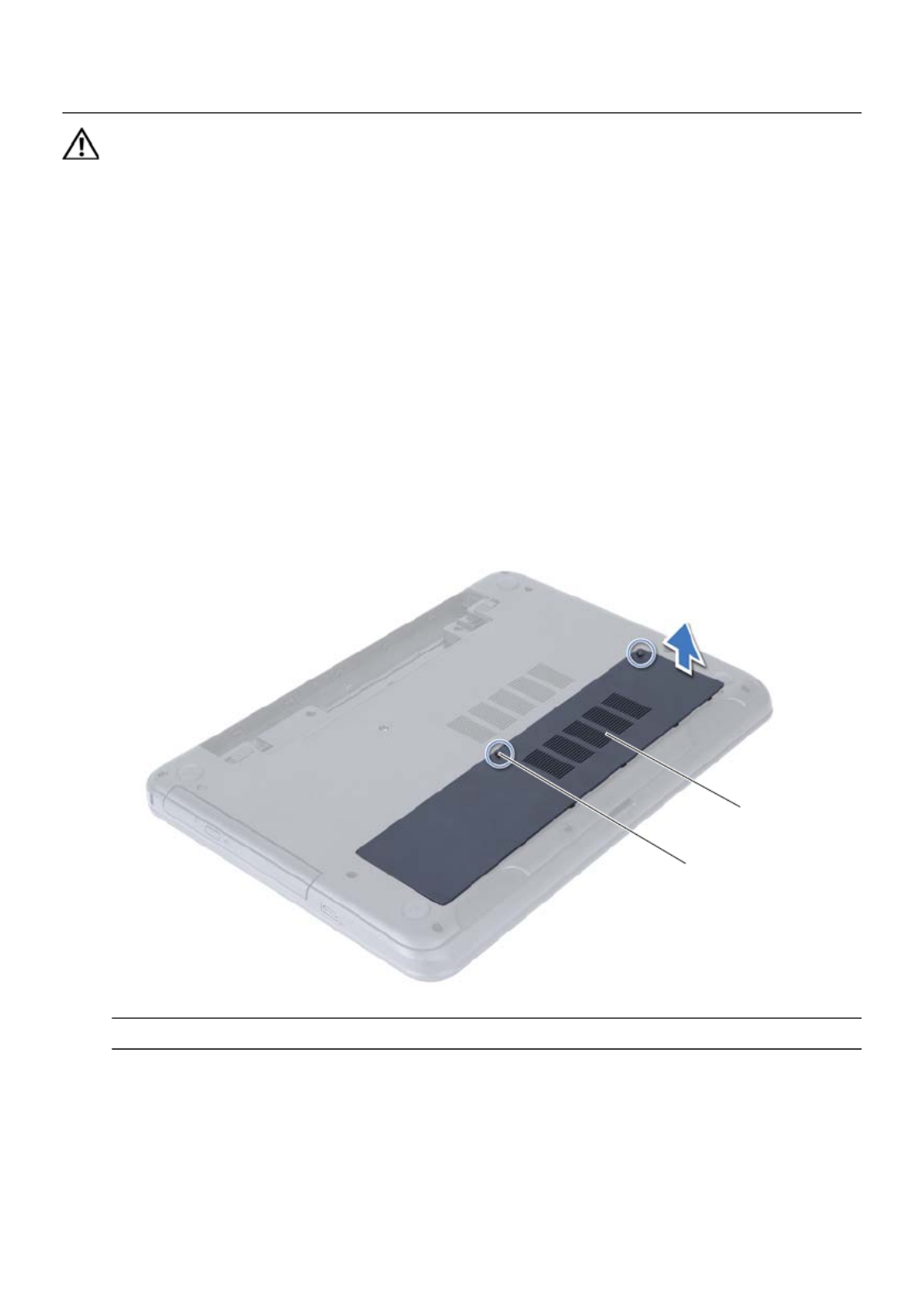
1Loosen the captive screw that secures the memory-module cover to
the computer base.
2Using your fingertips, lift the memory-module cover out of the slots on the
computer base.
1 captive screw 2 memory-module cover
2
1

16 | Removing the Memory Module(s)
3Use your fingertips to carefully spread apart the securing clips on each end of the
memory-module connector until the memory module pops up.
4Remove the memory module from the memory-module connector.
1 securing clips (2) 2 memory-module connector
3 memory module
1
3
2

Replacing the Memory Module(s) | 17
Replacing the Memory Module(s)
WARNING: Before working inside your computer, read the safety information
that shipped with your computer and follow the steps in "Before You Begin" on
page 7. After working inside your computer, follow the instructions in "After
Working Inside Your Computer" on page 9. For additional safety best practices
information, see the Regulatory Compliance Homepage at
dell.com/regulatory_compliance.
Procedure
1Align the notch on the memory module with the tab on the
memory-module connector.
2Slide the memory module firmly into the connector at a 45-degree angle
and press the memory module down until it clicks into place.
NOTE: If you do not hear the click, remove the memory module and reinstall it.
3Slide the tabs on the memory-module cover into the slots on the computer base
and snap the memory-module cover into place.
4Tighten the captive screw that secures the memory-module cover to
the computer base.
Postrequisites
1Replace the battery. See "Replacing the Battery" on page 13.
2Follow the instructions in "After Working Inside Your Computer" on page 9.

18 | Replacing the Memory Module(s)

Removing the Optical-Drive Assembly | 19
Removing the Optical-Drive Assembly
WARNING: Before working inside your computer, read the safety information
that shipped with your computer and follow the steps in "Before You Begin" on
page 7. After working inside your computer, follow the instructions in "After
Working Inside Your Computer" on page 9. For additional safety best practices
information, see the Regulatory Compliance Homepage at
dell.com/regulatory_compliance.
Prerequisites
1Remove the battery. See "Removing the Battery" on page 11.
Procedure
1Remove the screw that secures the optical-drive assembly to the computer base.
2Using your fingertips, slide the optical-drive assembly out of the optical-drive bay.
1 optical-drive assembly 2 screw
1
2

20 | Removing the Optical-Drive Assembly
3Remove the screws that secure the optical-drive bracket to
the optical-drive assembly.
4Remove the optical-drive bracket from the optical-drive assembly.
5Carefully pry the optical-drive bezel and remove it from the optical-drive assembly.
1 optical-drive bezel 2 optical drive
3 screws (2) 4 optical-drive bracket
3
1
2
4

Removing the Hard-Drive Assembly | 23
Removing the Hard-Drive Assembly
WARNING: Before working inside your computer, read the safety information
that shipped with your computer and follow the steps in "Before You Begin" on
page 7. After working inside your computer, follow the instructions in "After
Working Inside Your Computer" on page 9. For additional safety best practices
information, see the Regulatory Compliance Homepage at
dell.com/regulatory_compliance.
CAUTION: To avoid data loss, do not remove the hard drive while the computer is
in Sleep or On state.
CAUTION: Hard drives are extremely fragile. Exercise care when handling the
hard drive.
Prerequisites
1Remove the battery. See "Removing the Battery" on page 11.
2Follow the instructions from step 1 to step 2 in "Removing the Memory Module(s)"
on page 15.
Procedure
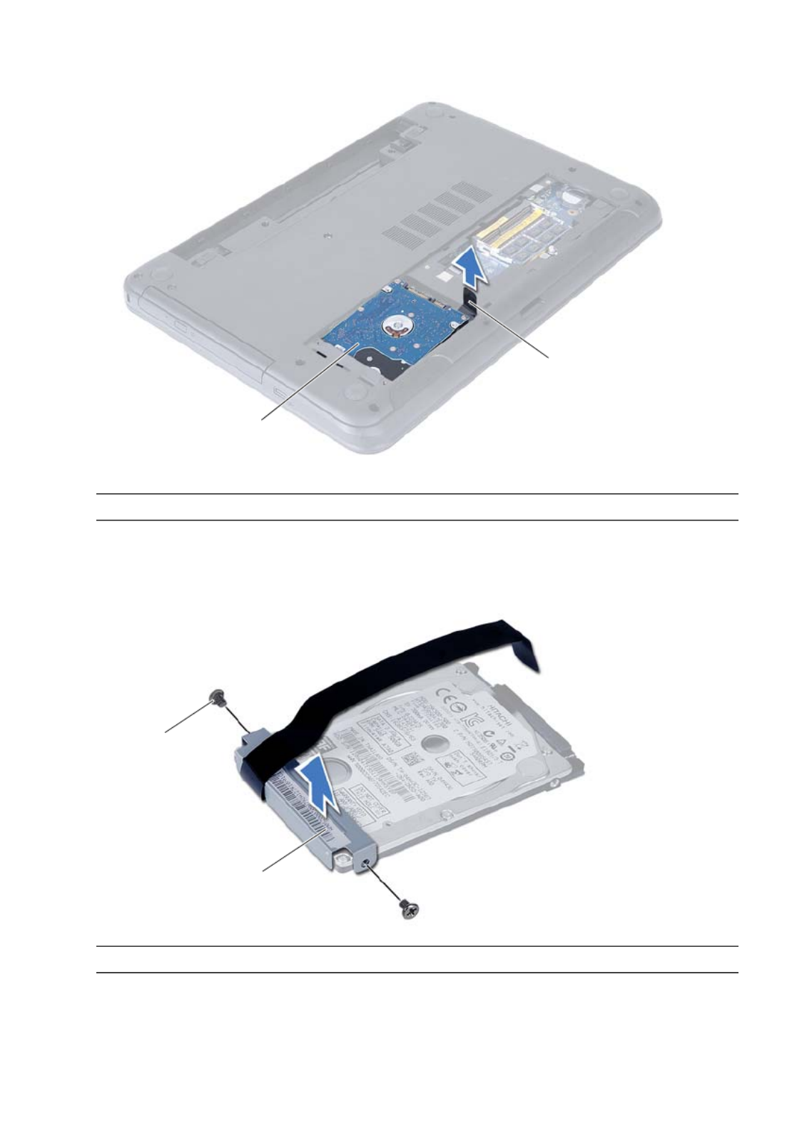
1Remove the screws that secure the hard-drive assembly to the computer base.
2Slide the hard-drive assembly forward to disconnect the hard-drive assembly from
the system board.
1 screws (2) 2 hard-drive assembly
12
24 | Removing the Hard-Drive Assembly
3Using the pull-tab, lift the hard-drive assembly out of the computer base.
4Remove the screws that secure the hard-drive bracket to the hard drive.
5Lift the hard-drive bracket off the hard drive.
1 hard-drive assembly 2 pull-tab
1 screws (2) 2 hard-drive bracket
2
1
2
1

Replacing the Hard-Drive Assembly | 25
Replacing the Hard-Drive Assembly
WARNING: Before working inside your computer, read the safety information
that shipped with your computer and follow the steps in "Before You Begin" on
page 7. After working inside your computer, follow the instructions in "After
Working Inside Your Computer" on page 9. For additional safety best practices
information, see the Regulatory Compliance Homepage at
dell.com/regulatory_compliance.
CAUTION: Hard drives are extremely fragile. Exercise care when handling the
hard drive.
Procedure
1Align the screw holes on the hard-drive bracket with the screw holes on
the hard drive.
2Replace the screws that secure the hard-drive bracket to the hard drive.
3Slide and place the hard-drive assembly in the hard-drive bay.
4Slide the hard-drive assembly backward to connect the hard-drive assembly to the
system board.
5Replace the screws that secure the hard-drive assembly to the computer base.
Postrequisites
1Follow the instructions from step 3 to step 4 in "Replacing the Memory Module(s)"
on page 17.
2Replace the battery. See "Replacing the Battery" on page 13.
3Follow the instructions in "After Working Inside Your Computer" on page 9.

26 | Replacing the Hard-Drive Assembly

Removing the Keyboard | 27
Removing the Keyboard
WARNING: Before working inside your computer, read the safety information
that shipped with your computer and follow the steps in "Before You Begin" on
page 7. After working inside your computer, follow the instructions in "After
Working Inside Your Computer" on page 9. For additional safety best practices
information, see the Regulatory Compliance Homepage at
dell.com/regulatory_compliance.
Prerequisites
1Remove the battery. See "Removing the Battery" on page 11.
Procedure
1Turn the computer over and open the display as far as possible.
2Using a plastic scribe, release the keyboard from the tabs on the
palm-rest assembly.
1 plastic scribe 2 tabs (9)
3 keyboard
1
23
28 | Removing the Keyboard
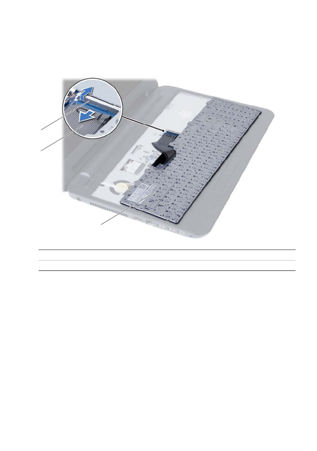
3 Lift and slide the keyboard towards the display to release the keyboard from the
palm-rest assembly.
4 Turn the keyboard over and place it on the palm-rest assembly.
5 Lift the connector latch and disconnect the keyboard from the connector on the
system board.
6 Lift the keyboard off the palm-rest assembly.
1 connector latch 2 keyboard cable
3 keyboard
1
2
3

Replacing the Keyboard | 29
Replacing the Keyboard
WARNING: Before working inside your computer, read the safety information
that shipped with your computer and follow the steps in "Before You Begin" on
page 7. After working inside your computer, follow the instructions in "After
Working Inside Your Computer" on page 9. For additional safety best practices
information, see the Regulatory Compliance Homepage at
dell.com/regulatory_compliance.
Procedure
1 Slide the keyboard cable into the connector on the system board and press down
on the connector latch to secure it.
2 Slide the tabs at the bottom of the keyboard into the slots on the
palm-rest assembly and place the keyboard on the palm-rest assembly.
3 Gently press around the edges of the keyboard to secure the keyboard under the
tabs on the palm-rest assembly.
Postrequisites
1 Replace the battery. See "Replacing the Battery" on page 13.
2 Follow the instructions in "After Working Inside Your Computer" on page 9.

30 | Replacing the Keyboard

Removing the Palm-Rest | 31
Removing the Palm-Rest
WARNING: Before working inside your computer, read the safety information
that shipped with your computer and follow the steps in "Before You Begin" on
page 7. After working inside your computer, follow the instructions in "After
Working Inside Your Computer" on page 9. For additional safety best practices
information, see the Regulatory Compliance Homepage at
dell.com/regulatory_compliance.
Prerequisites
1 Remove the battery. See "Removing the Battery" on page 11.
2 Follow the instructions from step 1 to step 2 in "Removing the Memory Module(s)"
on page 15.
3 Remove the optical-drive assembly. See "Removing the Optical-Drive Assembly" on
page 19.
4 Remove the keyboard. See "Removing the Keyboard" on page 27.
Procedure
1 Close the display and turn the computer over.
2 Remove the screws that secure the palm-rest to the computer base.
1 screws (12)
1

32 | Removing the Palm-Rest
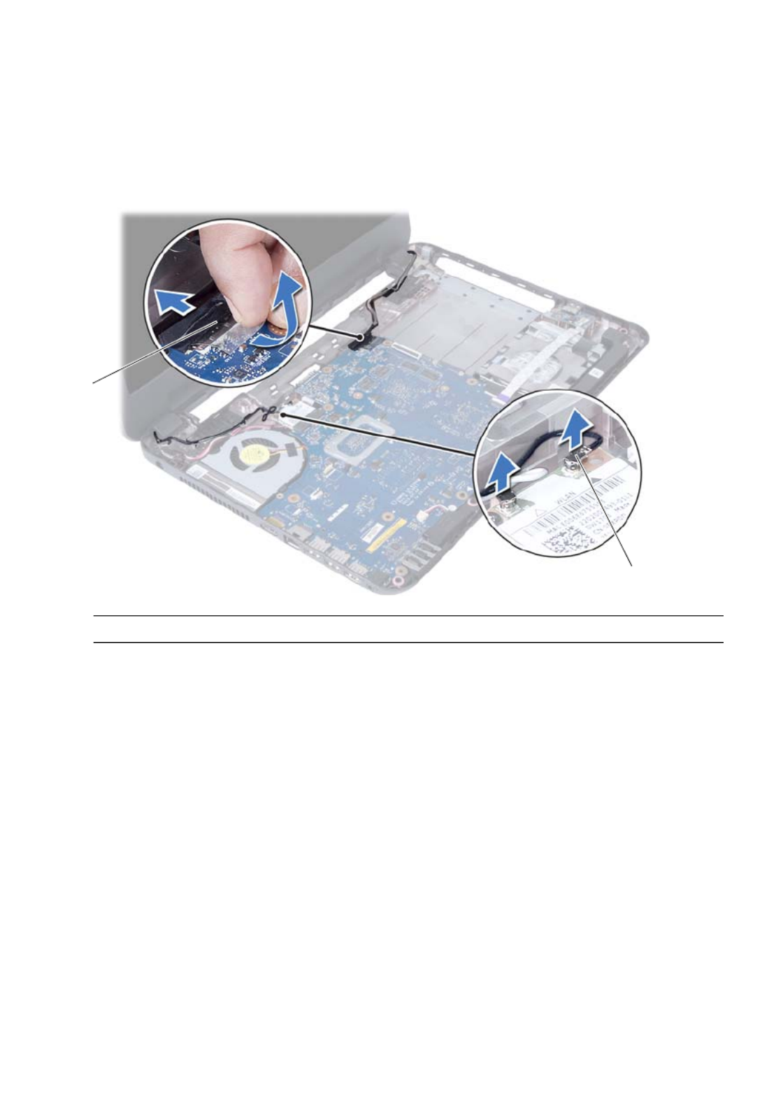
3 Turn the computer over and open the display as far as possible.
4 Lift the connector latches and pull the pull-tab to disconnect the touchpad cable
and the power-button cable from the system board.
1 touchpad cable 2 power-button cable
3 connector latches (2)
1
2
3

34 | Removing the Palm-Rest

Replacing the Palm-Rest | 35
Replacing the Palm-Rest
WARNING: Before working inside your computer, read the safety information
that shipped with your computer and follow the steps in "Before You Begin" on
page 7. After working inside your computer, follow the instructions in "After
Working Inside Your Computer" on page 9. For additional safety best practices
information, see the Regulatory Compliance Homepage at
dell.com/regulatory_compliance.
Procedure
1 Align the palm-rest over the computer base.
2 Press down on the palm-rest to snap it into place.
3 Slide the touchpad cable and the power-button cable into the connectors on the
system board and press down on the connector latches to secure the cables.
4 Replace the screws that secure the palm-rest to the system board.
5 Close the display and turn the computer over.
6 Replace the screws that secure the palm-rest to the computer base.
Postrequisites
1 Replace the keyboard. See "Replacing the Keyboard" on page 29.
2 Replace the optical-drive assembly. See "Replacing the Optical-Drive Assembly" on
page 21.
3 Follow the instructions from step 3 and step 4 in "Replacing the Memory Module(s)"
on page 17.
4 Replace the battery. See "Replacing the Battery" on page 13.
5 Follow the instructions in "After Working Inside Your Computer" on page 9.

36 | Replacing the Palm-Rest

Removing the Wireless Mini-Card | 37
Removing the Wireless Mini-Card
WARNING: Before working inside your computer, read the safety information
that shipped with your computer and follow the steps in "Before You Begin" on
page 7. After working inside your computer, follow the instructions in "After
Working Inside Your Computer" on page 9. For additional safety best practices
information, see the Regulatory Compliance Homepage at
dell.com/regulatory_compliance.
NOTE: Dell does not guarantee compatibility or provide support for
wireless mini-cards from sources other than Dell.
If you ordered a wireless mini-card with your computer, the card is already installed.
Your computer has a half wireless mini-card slot which supports a Wireless Local Area
Network (WLAN) + Bluetooth combo card.
Prerequisites
1Remove the battery. See "Removing the Battery" on page 11.
2Follow the instructions from step 1 to step 2 in "Removing the Memory Module(s)"
on page 15.
3Remove the optical-drive assembly. See "Removing the Optical-Drive Assembly" on
page 19.
4Remove the keyboard. See "Removing the Keyboard" on page 27.
5Remove the palm-rest. See "Removing the Palm-Rest" on page 31.

38 | Removing the Wireless Mini-Card
Procedure
1Disconnect the antenna cables from the connectors on the wireless mini-card.
2Remove the screw that secures the wireless mini-card to the
system-board connector.
3Slide and remove the wireless mini-card out of the system-board connector.
1 screw 2 antenna cables (2)
3 wireless mini-card
1 wireless mini-card 2 system-board connector
1
3
2
1
2

Replacing the Wireless Mini-Card | 39
Replacing the Wireless Mini-Card
WARNING: Before working inside your computer, read the safety information
that shipped with your computer and follow the steps in "Before You Begin" on
page 7. After working inside your computer, follow the instructions in "After
Working Inside Your Computer" on page 9. For additional safety best practices
information, see the Regulatory Compliance Homepage at
dell.com/regulatory_compliance.
Procedure
CAUTION: To avoid damage to the wireless mini-card, ensure that no cables are
placed under the wireless mini-card.
1Align the notch on the wireless mini-card with the tab on the
system-board connector.
2Insert the wireless mini-card connector at a 45-degree angle into the connector on
the system board.
3Press the other end of the wireless mini-card down into the slot on the
system board and replace the screw that secures the wireless mini-card to
the system board.
4Connect the antenna cables to the wireless mini-card.
The following table provides the antenna cable color schemes for the wireless
mini-card supported by your computer.
Connectors on the wireless mini-card Antenna cable color schemes
WLAN + Bluetooth (2 cables)
Main WLAN + Bluetooth (white triangle)
Auxiliary WLAN + Bluetooth (black triangle)
white
black

Removing the I/O Board | 41
Removing the I/O Board
WARNING: Before working inside your computer, read the safety information
that shipped with your computer and follow the steps in "Before You Begin" on
page 7. After working inside your computer, follow the instructions in "After
Working Inside Your Computer" on page 9. For additional safety best practices
information, see the Regulatory Compliance Homepage at
dell.com/regulatory_compliance.
Prerequisites
1Remove the battery. See "Removing the Battery" on page 11.
2Follow the instructions from step 1 to step 2 in "Removing the Memory Module(s)"
on page 15.
3Remove the optical-drive assembly. See "Removing the Optical-Drive Assembly" on
page 19.
4Remove the keyboard. See "Removing the Keyboard" on page 27.
5Remove the palm-rest. See "Removing the Palm-Rest" on page 31.

42 | Removing the I/O Board
Procedure
1Remove the screw that secures the I/O board to the computer base.
2Use the pull-tab to disconnect the I/O board cable from the connector on
the system board.
3Gently lift and remove the I/O board off the computer base.
1 I/O board 2 I/O board cable
3 screw
2
1
3

Replacing the I/O Board | 43
Replacing the I/O Board
WARNING: Before working inside your computer, read the safety information
that shipped with your computer and follow the steps in "Before You Begin" on
page 7. After working inside your computer, follow the instructions in "After
Working Inside Your Computer" on page 9. For additional safety best practices
information, see the Regulatory Compliance Homepage at
dell.com/regulatory_compliance.
Procedure
1Gently slide the I/O board below the tab that secures it and snap the I/O board
into place.
2Replace the screw that secures the I/O board to the computer base.
3Connect the I/O board cable to the connector on the I/O board.
Postrequisites
1Replace the palm-rest. See "Replacing the Palm-Rest" on page 35.
2Replace the keyboard. See "Replacing the Keyboard" on page 29.
3Replace the optical-drive assembly. See "Replacing the Optical-Drive Assembly" on
page 21.
4Follow the instructions from step 3 and step 4 in "Replacing the Memory Module(s)"
on page 17.
5Replace the battery. See "Replacing the Battery" on page 13.
6Follow the instructions in "After Working Inside Your Computer" on page 9.

44 | Replacing the I/O Board

Removing the System Board | 45
Removing the System Board
WARNING: Before working inside your computer, read the safety information
that shipped with your computer and follow the steps in "Before You Begin" on
page 7. After working inside your computer, follow the instructions in "After
Working Inside Your Computer" on page 9. For additional safety best practices
information, see the Regulatory Compliance Homepage at
dell.com/regulatory_compliance.
NOTE: Your computer’s Service Tag is stored in the system board. You must enter
the Service Tag in system setup after you replace the system board. For more
information, see "Entering the Service Tag in system setup" on page 49.
NOTE: Before disconnecting the cables from the system board, note the location
of the connectors so that you can reconnect them correctly after you replace the
system board.
Prerequisites
1Remove the battery. See "Removing the Battery" on page 11.
2Follow the instructions from step 1 to step 2 in "Removing the Memory Module(s)"
on page 15.
3Remove the hard-drive assembly. See "Removing the Hard-Drive Assembly" on
page 23.
4Remove the optical-drive assembly. See "Removing the Optical-Drive Assembly" on
page 19.
5Remove the keyboard. See "Removing the Keyboard" on page 27.
6Remove the palm-rest. See "Removing the Palm-Rest" on page 31.
7Remove the wireless Mini-Card. See "Removing the Wireless Mini-Card" on
page 37.

46 | Removing the System Board
Procedure
1Peel the tape that secures the display cable to the system board.
2Disconnect the display cable from the connector on the system board.
3Disconnect the power adapter-port cable, speaker cable, and the I/O board cable
from the system board.
1 display cable 2 tape
3 power-adapter-port cable 4 speaker cable
5 I/O board cable
1
2
3
4
5

48 | Removing the System Board

Replacing the System Board | 49
Replacing the System Board
WARNING: Before working inside your computer, read the safety information
that shipped with your computer and follow the steps in "Before You Begin" on
page 7. After working inside your computer, follow the instructions in "After
Working Inside Your Computer" on page 9. For additional safety best practices
information, see the Regulatory Compliance Homepage at
dell.com/regulatory_compliance.
NOTE: Your computer’s Service Tag is stored in the system board. You must enter
the Service Tag in the system setup after you replace the system board.
Procedure
1Align the screw hole on the system board with the screw hole on the
computer base.
2Replace the screw that secures the system board to the computer base.
3Connect the power-adapter-port cable, speaker cable, and the I/O board cable to
the connectors on the system board.
4Connect the display cable to the system board.
5Adhere the tape that secures the display cable to the system board.
Postrequisites
1Replace the wireless Mini-Card. See "Replacing the Wireless Mini-Card" on page 39.
2Replace the palm-rest. See "Replacing the Palm-Rest" on page 35.
3Replace the keyboard. See "Replacing the Keyboard" on page 29.
4Replace the optical-drive assembly. See "Replacing the Optical-Drive Assembly" on
page 21.
5Replace the hard-drive assembly. See "Replacing the Hard-Drive Assembly" on
page 25.
6Follow the instructions from step 3 and step 4 in "Replacing the Memory Module(s)"
on page 17.
7Replace the battery. See "Replacing the Battery" on page 13.
8Follow the instructions in "After Working Inside Your Computer" on page 9.
Entering the Service Tag in system setup
1Turn on the computer.
2Press <F2> during POST to enter system setup.
3Navigate to the Main tab and enter your computer’s Service Tag in the
Service Tag Input field.

50 | Replacing the System Board

Removing the Coin-Cell Battery | 51
Removing the Coin-Cell Battery
WARNING: Before working inside your computer, read the safety information
that shipped with your computer and follow the steps in "Before You Begin" on
page 7. After working inside your computer, follow the instructions in "After
Working Inside Your Computer" on page 9. For additional safety best practices
information, see the Regulatory Compliance Homepage at
dell.com/regulatory_compliance.
WARNING: The coin-cell battery may explode if installed incorrectly.
Replace the coin-cell battery only with the same or equivalent type. Discard used
coin-cell batteries according to the manufacturer’s instructions.
CAUTION: Removing the coin-cell battery resets the BIOS settings to default. It is
recommended that you note the BIOS settings before removing the coin-cell
battery.
Prerequisites
1Remove the battery. See "Removing the Battery" on page 11.
2Follow the instructions from step 1 to step 2 in "Removing the Memory Module(s)"
on page 15.
3Remove the hard-drive assembly. See "Removing the Hard-Drive Assembly" on
page 23.
4Remove the optical-drive assembly. See "Removing the Optical-Drive Assembly" on
page 19.
5Remove the keyboard. See "Removing the Keyboard" on page 27.
6Remove the palm-rest. See "Removing the Palm-Rest" on page 31.
7Remove the system board. See "Removing the System Board" on page 45.

52 | Removing the Coin-Cell Battery
Procedure
1Turn the system board over and place it on a flat surface.
2Using a plastic scribe, gently pry out the coin-cell battery out of the battery socket
on the system board.
1 plastic scribe 2 coin-cell battery
1
2

Replacing the Coin-Cell Battery | 53
Replacing the Coin-Cell Battery
WARNING: Before working inside your computer, read the safety information
that shipped with your computer and follow the steps in "Before You Begin" on
page 7. After working inside your computer, follow the instructions in "After
Working Inside Your Computer" on page 9. For additional safety best practices
information, see the Regulatory Compliance Homepage at
dell.com/regulatory_compliance.
WARNING: The battery may explode if installed incorrectly. Replace the battery
only with the same or equivalent type. Discard used batteries according to the
manufacturer’s instructions.
Procedure
With the positive-side facing up, snap the coin-cell battery into the battery
socket on the system board.
Postrequisites
1Replace the system board. See "Replacing the System Board" on page 49.
2Replace the palm-rest. See "Replacing the Palm-Rest" on page 35.
3Replace the keyboard. See "Replacing the Keyboard" on page 29.
4Replace the optical-drive assembly. See "Replacing the Optical-Drive Assembly" on
page 21.
5Replace the hard-drive assembly. See "Replacing the Hard-Drive Assembly" on
page 25.
6Follow the instructions from step 3 and step 4 in "Replacing the Memory Module(s)"
on page 17.
7Replace the battery. See "Replacing the Battery" on page 13.
8Follow the instructions in "After Working Inside Your Computer" on page 9.

54 | Replacing the Coin-Cell Battery

Removing the Heat-Sink | 55
Removing the Heat-Sink
WARNING: Before working inside your computer, read the safety information
that shipped with your computer and follow the steps in "Before You Begin" on
page 7. After working inside your computer, follow the instructions in "After
Working Inside Your Computer" on page 9. For additional safety best practices
information, see the Regulatory Compliance Homepage at
dell.com/regulatory_compliance.
Prerequisites
1Remove the battery. See "Removing the Battery" on page 11.
1Follow the instructions from step 1 to step 2 in "Removing the Memory Module(s)"
on page 15.
2Remove the hard-drive assembly. See "Removing the Hard-Drive Assembly" on
page 23.
3Remove the optical-drive assembly. See "Removing the Optical-Drive Assembly" on
page 19.
4Remove the keyboard. See "Removing the Keyboard" on page 27.
5Remove the palm-rest. See "Removing the Palm-Rest" on page 31.
6Remove the wireless mini-card. See "Removing the Wireless Mini-Card" on page 37.
7Remove the system board. See "Removing the System Board" on page 45.

56 | Removing the Heat-Sink
Procedure
1Turn the system board over and place the system board on a flat surface.
2In sequential order (indicated on the heat-sink), remove the screws that secure the
heat-sink to the system board.
3Lift the heat-sink off the system board.
1 screw (6) 2 fan
1
2

Replacing the Heat-Sink | 57
Replacing the Heat-Sink
WARNING: Before working inside your computer, read the safety information
that shipped with your computer and follow the steps in "Before You Begin" on
page 7. After working inside your computer, follow the instructions in "After
Working Inside Your Computer" on page 9. For additional safety best practices
information, see the Regulatory Compliance Homepage at
dell.com/regulatory_compliance.
Procedure
1Clean the thermal grease from the bottom of the heat-sink and reapply it.
2Align the screw holes on the heat-sink with the screw holes on the system board.
3In sequential order (indicated on the heat-sink), replace the screws that secure the
heat-sink to the system board
Postrequisites
1Replace the system board. See "Replacing the System Board" on page 49.
2Replace the wireless mini-card. See "Replacing the Wireless Mini-Card" on page 39.
3Replace the palm-rest. See "Replacing the Palm-Rest" on page 35.
4Replace the keyboard. See "Replacing the Keyboard" on page 29.
5Replace the optical-drive assembly. See "Replacing the Optical-Drive Assembly" on
page 21.
6Replace the hard-drive assembly. See "Replacing the Hard-Drive Assembly" on
page 25.
7Follow the instructions from step 3 and step 4 in "Replacing the Memory Module(s)"
on page 17.
8Replace the battery. See "Replacing the Battery" on page 13.
9Follow the instructions in "After Working Inside Your Computer" on page 9.

58 | Replacing the Heat-Sink

Removing the Fan | 59
Removing the Fan
WARNING: Before working inside your computer, read the safety information
that shipped with your computer and follow the steps in "Before You Begin" on
page 7. After working inside your computer, follow the instructions in "After
Working Inside Your Computer" on page 9. For additional safety best practices
information, see the Regulatory Compliance Homepage at
dell.com/regulatory_compliance.
Prerequisites
1Remove the battery. See "Removing the Battery" on page 11.
2Follow the instructions from step 1 to step 2 in "Removing the Memory Module(s)"
on page 15.
3Remove the hard-drive assembly. See "Removing the Hard-Drive Assembly" on
page 23.
4Remove the optical-drive assembly. See "Removing the Optical-Drive Assembly" on
page 19.
5Remove the keyboard. See "Removing the Keyboard" on page 27.
6Remove the palm-rest. See "Removing the Palm-Rest" on page 31.
7Remove the wireless mini-card. See "Removing the Wireless Mini-Card" on page 37.
8Remove the system board. See "Removing the System Board" on page 45.

Replacing the Fan | 61
Replacing the Fan
WARNING: Before working inside your computer, read the safety information
that shipped with your computer and follow the steps in "Before You Begin" on
page 7. After working inside your computer, follow the instructions in "After
Working Inside Your Computer" on page 9. For additional safety best practices
information, see the Regulatory Compliance Homepage at
dell.com/regulatory_compliance.
Procedure
1Align the screw holes on the fan with the screw holes on the system board.
2Replace the screw that secures the fan to the system board.
3Connect the fan cable to the connector on the system-board.
Postrequisites
1Replace the system board. See "Replacing the System Board" on page 49.
2Replace the wireless mini-card. See "Replacing the Wireless Mini-Card" on page 39.
3Replace the palm-rest. See "Replacing the Palm-Rest" on page 35.
4Replace the keyboard. See "Replacing the Keyboard" on page 29.
5Replace the optical-drive assembly. See "Replacing the Optical-Drive Assembly" on
page 21.
6Replace the hard-drive assembly. See "Replacing the Hard-Drive Assembly" on
page 25.
7Follow the instructions from step 3 and step 4 in "Replacing the Memory Module(s)"
on page 17.
8Replace the battery. See "Replacing the Battery" on page 13.
9Follow the instructions in "After Working Inside Your Computer" on page 9.

62 | Replacing the Fan

Removing the Speakers | 63
Removing the Speakers
WARNING: Before working inside your computer, read the safety information
that shipped with your computer and follow the steps in "Before You Begin" on
page 7. After working inside your computer, follow the instructions in "After
Working Inside Your Computer" on page 9. For additional safety best practices
information, see the Regulatory Compliance Homepage at
dell.com/regulatory_compliance.
Prerequisites
1Remove the battery. See "Removing the Battery" on page 11.
2Follow the instructions from step 1 to step 2 in "Removing the Memory Module(s)"
on page 15.
3Remove the hard-drive assembly. See "Removing the Hard-Drive Assembly" on
page 23.
4Remove the optical-drive assembly. See "Removing the Optical-Drive Assembly" on
page 19.
5Remove the keyboard. See "Removing the Keyboard" on page 27.
6Remove the palm-rest. See "Removing the Palm-Rest" on page 31.
7Remove the wireless mini-card. See "Removing the Wireless Mini-Card" on page 37.
8Remove the system board. See "Removing the System Board" on page 45.

64 | Removing the Speakers
Procedure
1Peel the tape that secures the LED silicon tubes to the computer base.
2Lift and remove the LED silicon tubes off the computer base.
1 tape 2 LED silicon tubes
1
2

Removing the Speakers | 65
3 Note the speaker cable routing and remove the cable from the routing guides on
the computer base.
4 Lift the speakers, along with the speaker cable, off the computer base.
1 speaker cable routing 2 speakers (2)
1
2

66 | Removing the Speakers

Replacing the Speakers | 67
Replacing the Speakers
WARNING: Before working inside your computer, read the safety information
that shipped with your computer and follow the steps in "Before You Begin" on
page 7. After working inside your computer, follow the instructions in "After
Working Inside Your Computer" on page 9. For additional safety best practices
information, see the Regulatory Compliance Homepage at
dell.com/regulatory_compliance.
Procedure
1 Align the speakers on the computer base.
2 Route the speakers cable through the routing guides on the computer base.
3 Replace the LED silicon tubes to the computer base.
4 Adhere the tape that secures the LED silicon tubes to the computer base.
Postrequisites
1 Replace the system board. See "Replacing the System Board" on page 49.
2 Replace the wireless mini-card. See "Replacing the Wireless Mini-Card" on page 39.
3 Replace the palm-rest. See "Replacing the Palm-Rest" on page 35.
4 Replace the keyboard. See "Replacing the Keyboard" on page 29.
5 Replace the optical-drive assembly. See "Replacing the Optical-Drive Assembly" on
page 21.
6 Replace the hard-drive assembly. See "Replacing the Hard-Drive Assembly" on
page 25.
7 Follow the instructions from step 3 and step 4 in "Replacing the Memory Module(s)"
on page 17.
8 Replace the battery. See "Replacing the Battery" on page 13.
9 Follow the instructions in "After Working Inside Your Computer" on page 9.
70 | Removing the Display Assembly
Procedure
1 Peel the tape that secures the display cable to the system board.
2 Disconnect the display cable from the connectors on the system board.
3 Disconnect the wireless mini-card cables from the connectors on the
wireless mini-card.
1 display cable 2 wireless mini-card cables (2)
1
2

Removing the Display Assembly | 71
4 Move aside the power adapter-port cable from the screws.
5 Remove the screws that secure the display assembly to the computer base.
6 Lift the display assembly off the computer base.
1 display assembly 2 screws (3)
3 power adapter-port cable
1
2
3

72 | Removing the Display Assembly

Replacing the Display Assembly | 73
Replacing the Display Assembly
WARNING: Before working inside your computer, read the safety information
that shipped with your computer and follow the steps in "Before You Begin" on
page 7. After working inside your computer, follow the instructions in "After
Working Inside Your Computer" on page 9. For additional safety best practices
information, see the Regulatory Compliance Homepage at
dell.com/regulatory_compliance.
Procedure
1 Place the display assembly on the computer base and align the screw holes on the
display assembly with the screw holes on the computer base.
2 Replace the screws that secure the display assembly to the computer base.
3 Connect the wireless mini-card cables to the connectors on the wireless mini-card.
4 Connect the display cable to the connector on the system board.
5 Adhere the tape that secures the display cable to the system board.
Postrequisites
1 Replace the palm-rest. See "Replacing the Palm-Rest" on page 35.
2 Replace the keyboard. See "Replacing the Keyboard" on page 29.
3 Replace the optical-drive assembly.
See "Replacing the Optical-Drive Assembly" on page 21.
4 Replace the hard-drive assembly. See "Replacing the Hard-Drive Assembly" on
page 25.
5 Follow the instructions from step 3 and step 4 in "Replacing the Memory Module(s)"
on page 17.
6 Replace the battery. See "Replacing the Battery" on page 13.
7 Follow the instructions in "After Working Inside Your Computer" on page 9.

Removing the Display Bezel | 75
Removing the Display Bezel
WARNING: Before working inside your computer, read the safety information
that shipped with your computer and follow the steps in "Before You Begin" on
page 7. After working inside your computer, follow the instructions in "After
Working Inside Your Computer" on page 9. For additional safety best practices
information, see the Regulatory Compliance Homepage at
dell.com/regulatory_compliance.
Prerequisites
1 Remove the battery. See "Removing the Battery" on page 11.
2 Follow the instructions from step 1 to step 2 in "Removing the Memory Module(s)"
on page 15.
3 Remove the hard-drive assembly. See "Removing the Hard-Drive Assembly" on
page 23.
4 Remove the optical-drive assembly. See "Removing the Optical-Drive Assembly" on
page 19.
5 Remove the keyboard. See "Removing the Keyboard" on page 27.
6 Remove the palm-rest. See "Removing the Palm-Rest" on page 31.
7 Remove the display assembly. See "Removing the Display Assembly" on page 69.

76 | Removing the Display Bezel
Procedure
1 Press the hinge covers on the sides and lift the hinge covers to remove it from the
display assembly.
2 Using your fingertips, carefully pry up the inside edge of the display bezel.
3 Remove the display bezel off the display back-cover.
1 hinge covers (2)
1 display bezel
1
1

Replacing the Display Bezel | 77
Replacing the Display Bezel
WARNING: Before working inside your computer, read the safety information
that shipped with your computer and follow the steps in "Before You Begin" on
page 7. After working inside your computer, follow the instructions in "After
Working Inside Your Computer" on page 9. For additional safety best practices
information, see the Regulatory Compliance Homepage at
dell.com/regulatory_compliance.
Procedure
1 Align the display bezel with the display back-cover, and gently snap the
display bezel into place.
2 Align the hinge covers with the hinges on the display assembly and snap the
hinge covers into place.
Postrequisites
1 Replace the display assembly. See "Replacing the Display Assembly" on page 73.
2 Replace the palm-rest. See "Replacing the Palm-Rest" on page 35.
3 Replace the keyboard. See "Replacing the Keyboard" on page 29.
4 Replace the optical-drive assembly. See "Replacing the Optical-Drive Assembly" on
page 21.
5 Replace the hard-drive assembly. See "Replacing the Hard-Drive Assembly" on
page 25.
6 Follow the instructions from step 3 and step 4 in "Replacing the Memory Module(s)"
on page 17.
7 Replace the battery. See "Replacing the Battery" on page 13.
8 Follow the instructions in "After Working Inside Your Computer" on page 9.

78 | Replacing the Display Bezel

Removing the Display Hinges | 79
Removing the Display Hinges
WARNING: Before working inside your computer, read the safety information
that shipped with your computer and follow the steps in "Before You Begin" on
page 7. After working inside your computer, follow the instructions in "After
Working Inside Your Computer" on page 9. For additional safety best practices
information, see the Regulatory Compliance Homepage at
dell.com/regulatory_compliance.
Prerequisites
1 Remove the battery. See "Removing the Battery" on page 11.
2 Follow the instructions from step 1 to step 2 in "Removing the Memory Module(s)"
on page 15.
3 Remove the hard-drive assembly. See "Removing the Hard-Drive Assembly" on
page 23.
4 Remove the optical-drive assembly. See "Removing the Optical-Drive Assembly" on
page 19.
5 Remove the keyboard. See "Removing the Keyboard" on page 27.
6 Remove the palm-rest. See "Removing the Palm-Rest" on page 31.
7 Remove the display assembly. See "Removing the Display Assembly" on page 69.
8 Remove the display bezel. See "Removing the Display Bezel" on page 75.

80 | Removing the Display Hinges
Procedure
1Remove the screws that secure the display hinges to the display panel.
2Lift the display hinges off the display back-cover.
1 screws (8) 2 display hinges (2)
2
1

Replacing the Display Hinges | 81
Replacing the Display Hinges
WARNING: Before working inside your computer, read the safety information
that shipped with your computer and follow the steps in "Before You Begin" on
page 7. After working inside your computer, follow the instructions in "After
Working Inside Your Computer" on page 9. For additional safety best practices
information, see the Regulatory Compliance Homepage at
dell.com/regulatory_compliance.
Procedure
1Align the screw holes on the display hinges with the screw holes on
the display back-cover.
2Replace the screws that secure the display hinges to the display back-cover.
Postrequisites
1Replace the display bezel. See "Replacing the Display Bezel" on page 77.
2Replace the display assembly. See "Replacing the Display Assembly" on page 73.
3Replace the palm-rest. See "Replacing the Palm-Rest" on page 35.
4Replace the keyboard. See "Replacing the Keyboard" on page 29.
5Replace the optical-drive assembly. See "Replacing the Optical-Drive Assembly" on
page 21.
6Replace the hard-drive assembly. See "Replacing the Hard-Drive Assembly" on
page 25.
7Follow the instructions from step 3 and step 4 in "Replacing the Memory Module(s)"
on page 17.
8Replace the battery. See "Replacing the Battery" on page 13.
9Follow the instructions in "After Working Inside Your Computer" on page 9.

82 | Replacing the Display Hinges

Removing the Display Panel | 83
Removing the Display Panel
WARNING: Before working inside your computer, read the safety information
that shipped with your computer and follow the steps in "Before You Begin" on
page 7. After working inside your computer, follow the instructions in "After
Working Inside Your Computer" on page 9. For additional safety best practices
information, see the Regulatory Compliance Homepage at
dell.com/regulatory_compliance.
Prerequisites
1Remove the battery. See "Removing the Battery" on page 11.
2Follow the instructions from step 1 to step 2 in "Removing the Memory Module(s)"
on page 15.
3Remove the hard-drive assembly. See "Removing the Hard-Drive Assembly" on
page 23.
4Remove the optical-drive assembly. See "Removing the Optical-Drive Assembly" on
page 19.´
5Remove the keyboard. See "Removing the Keyboard" on page 27.
6Remove the palm-rest. See "Removing the Palm-Rest" on page 31.
7Remove the display assembly. See "Removing the Display Assembly" on page 69.
8Remove the display bezel. See "Removing the Display Bezel" on page 75.
9Remove the display hinges. See "Removing the Display Hinges" on page 79.

84 | Removing the Display Panel
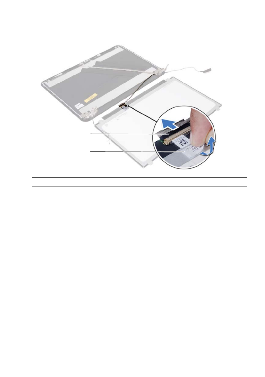
Procedure
1Remove the screws that secure the display panel to the display back-cover.
2Gently lift the display panel and turn it over.
1 display back-cover 2 display panel
3 screws (4)
3
2
1
Removing the Display Panel | 85
3Peel the tape that is adhered over the display cable.
4Disconnect the display cable from the connector on the display panel.
1 display cable 2 tape
2
1

86 | Removing the Display Panel

88 | Replacing the Display Panel
Specyfikacje produktu
| Marka: | Dell |
| Kategoria: | laptop |
| Model: | Inspiron 5521 |
Potrzebujesz pomocy?
Jeśli potrzebujesz pomocy z Dell Inspiron 5521, zadaj pytanie poniżej, a inni użytkownicy Ci odpowiedzą
Instrukcje laptop Dell

3 Kwietnia 2025
13 Marca 2025
26 Lutego 2025
22 Lutego 2025
6 Lutego 2025
6 Lutego 2025
28 Stycznia 2025
15 Stycznia 2025
10 Stycznia 2025
30 Grudnia 2025
Instrukcje laptop
- laptop Sony
- laptop Samsung
- laptop Fellowes
- laptop LG
- laptop Xiaomi
- laptop Huawei
- laptop Lenovo
- laptop Gigabyte
- laptop Acer
- laptop Fujitsu
- laptop Panasonic
- laptop Viewsonic
- laptop Asus
- laptop Medion
- laptop MSI
- laptop Toshiba
- laptop Haier
- laptop HP
- laptop Prixton
- laptop Hyundai
- laptop Honor
- laptop Tripp Lite
- laptop Zebra
- laptop Schneider
- laptop Thomson
- laptop Pyle
- laptop Apple
- laptop Razer
- laptop ADATA
- laptop GoClever
- laptop SPC
- laptop NEC
- laptop Oregon Scientific
- laptop Jay-Tech
- laptop Microsoft
- laptop ECS
- laptop XPG
- laptop Denver
- laptop Lexibook
- laptop Micromax
- laptop Odys
- laptop TechBite
- laptop TrekStor
- laptop Alienware
- laptop Airis
- laptop Emachines
- laptop Hähnel
- laptop Sylvania
- laptop Coby
- laptop Evga
- laptop Naxa
- laptop Ricatech
- laptop Mpman
- laptop Vizio
- laptop Targa
- laptop Peaq
- laptop Ematic
- laptop Hannspree
- laptop Inovia
- laptop Ergotron
- laptop Ibm
- laptop Atdec
- laptop Packard Bell
- laptop Compaq
- laptop SIIG
- laptop Hercules
- laptop Kogan
- laptop Getac
- laptop Vulcan
- laptop System76
- laptop General Dynamics Itronix
- laptop CTL
- laptop Everex
- laptop Olidata
- laptop Dynabook
- laptop Hamilton Buhl
- laptop AORUS
- laptop Humanscale
- laptop Aplic
- laptop Schenker
Najnowsze instrukcje dla laptop

2 Kwietnia 2025

28 Marca 2025

28 Marca 2025
26 Marca 2025
7 Marca 2025

4 Marca 2025
1 Marca 2025
23 Lutego 2025
23 Lutego 2025
22 Lutego 2025