Instrukcja obsługi Asus MAXIMUS VI HERO
Asus
płyta główna
MAXIMUS VI HERO
Przeczytaj poniżej 📖 instrukcję obsługi w języku polskim dla Asus MAXIMUS VI HERO (182 stron) w kategorii płyta główna. Ta instrukcja była pomocna dla 4 osób i została oceniona przez 2 użytkowników na średnio 4.5 gwiazdek
Strona 1/182

Motherboard
MAXIMUS VI
HERO

ii
E8459
Revised Edition V2
June 2013
Copyright © 2013 ASUSTeK COMPUTER INC. All Rights Reserved.
No part of this manual, including the products and software described in it, may be reproduced,
transmitted, transcribed, stored in a retrieval system, or translated into any language in any form or by any
means, except documentation kept by the purchaser for backup purposes, without the express written
permission of ASUSTeK COMPUTER INC. (“ASUS”).
Product warranty or service will not be extended if: (1) the product is repaired, modied or altered, unless
such repair, modication of alteration is authorized in writing by ASUS; or (2) the serial number of the
product is defaced or missing.
ASUS PROVIDES THIS MANUAL “AS IS” WITHOUT WARRANTY OF ANY KIND, EITHER EXPRESS
OR IMPLIED, INCLUDING BUT NOT LIMITED TO THE IMPLIED WARRANTIES OR CONDITIONS OF
MERCHANTABILITY OR FITNESS FOR A PARTICULAR PURPOSE. IN NO EVENT SHALL ASUS, ITS
DIRECTORS, OFFICERS, EMPLOYEES OR AGENTS BE LIABLE FOR ANY INDIRECT, SPECIAL,
INCIDENTAL, OR CONSEQUENTIAL DAMAGES (INCLUDING DAMAGES FOR LOSS OF PROFITS,
LOSS OF BUSINESS, LOSS OF USE OR DATA, INTERRUPTION OF BUSINESS AND THE LIKE),
EVEN IF ASUS HAS BEEN ADVISED OF THE POSSIBILITY OF SUCH DAMAGES ARISING FROM ANY
DEFECT OR ERROR IN THIS MANUAL OR PRODUCT.
SPECIFICATIONS AND INFORMATION CONTAINED IN THIS MANUAL ARE FURNISHED FOR
INFORMATIONAL USE ONLY, AND ARE SUBJECT TO CHANGE AT ANY TIME WITHOUT NOTICE,
AND SHOULD NOT BE CONSTRUED AS A COMMITMENT BY ASUS. ASUS ASSUMES NO
RESPONSIBILITY OR LIABILITY FOR ANY ERRORS OR INACCURACIES THAT MAY APPEAR IN THIS
MANUAL, INCLUDING THE PRODUCTS AND SOFTWARE DESCRIBED IN IT.
Products and corporate names appearing in this manual may or may not be registered trademarks or
copyrights of their respective companies, and are used only for identication or explanation and to the
owners’ benet, without intent to infringe.
Offer to Provide Source Code of Certain Software
This product contains copyrighted software that is licensed under the General Public License (“GPL”),
under the Lesser General Public License Version (“LGPL”) and/or other Free Open Source Software
Licenses. Such software in this product is distributed without any warranty to the extent permitted by the
applicable law. Copies of these licenses are included in this product.
Where the applicable license entitles you to the source code of such software and/or other additional data,
you may obtain it for a period of three years after our last shipment of the product, either
(1) for free by downloading it from http://support.asus.com/download
or
(2) for the cost of reproduction and shipment, which is dependent on the preferred carrier and the location
where you want to have it shipped to, by sending a request to:
ASUSTeK Computer Inc.
Legal Compliance Dept.
15 Li Te Rd.,
Beitou, Taipei 112
Taiwan
In your request please provide the name, model number and version, as stated in the About Box of the
product for which you wish to obtain the corresponding source code and your contact details so that we
can coordinate the terms and cost of shipment with you.
The source code will be distributed WITHOUT ANY WARRANTY and licensed under the same license as
the corresponding binary/object code.
This offer is valid to anyone in receipt of this information.
ASUSTeK is eager to duly provide complete source code as required under various Free Open Source
Software licenses. If however you encounter any problems in obtaining the full corresponding source
code we would be much obliged if you give us a notication to the email address gpl@asus.com, stating
the product and describing the problem (please DO NOT send large attachments such as source code
archives, etc. to this email address).

iii
Contents
Safety information ...................................................................................................... vi
About this guide ........................................................................................................ vii
MAXIMUS VI HERO specications summary .......................................................... ix
Package contents ..................................................................................................... xiii
Installation tools and components ......................................................................... xiv
Chapter 1: Product Introduction
1.1 Special features.......................................................................................... 1-1
1.1.1 Product highlights........................................................................ 1-1
1.1.2 ROG Gaming Features ...............................................................1-2
1.1.3 ROG Exclusive Features.............................................................1-3
1.1.4 ASUS Special Features ..............................................................1-3
1.1.5 ROG rich bundled software ......................................................... 1-4
1.2 Motherboard overview ...............................................................................1-5
1.2.1 Before you proceed .....................................................................1-5
1.2.2 Motherboard layout .....................................................................1-6
1.2.3 Central Processing Unit (CPU) ................................................... 1-8
1.2.4 System memory ..........................................................................1-9
1.2.5 Expansion slots ......................................................................... 1-23
1.2.6 Onboard buttons .......................................................................1-25
1.2.7 Jumper ...................................................................................... 1-28
1.2.8 Onboard LEDs .......................................................................... 1-29
1.2.9 Internal connectors.................................................................... 1-38
Chapter 2: Basic Installation
2.1 Building your PC system...........................................................................2-1
2.1.1 Motherboard installation ..............................................................2-1
2.1.2 CPU installation........................................................................... 2-3
2.1.3 CPU heatsink and fan assembly installation ............................... 2-4
2.1.4 DIMM installation......................................................................... 2-6
2.1.5 ATX Power connection ................................................................2-7
2.1.6 SATA device connection ..............................................................2-8
2.1.7 Front I/O Connector .................................................................... 2-9
2.1.8 Expansion Card installation.......................................................2-10
2.2 BIOS update utility ................................................................................... 2-11
2.3 Motherboard rear and audio connections ............................................. 2-12
2.3.1 Rear I/O connection ..................................................................2-12
2.3.2 Audio I/O connections ............................................................... 2-13
2.4 Starting up for the rst time .................................................................... 2-17
2.5 Turning off the computer .........................................................................2-17

iv
Chapter 3: BIOS setup
3.1 Knowing BIOS ............................................................................................3-1
3.2 BIOS setup program .................................................................................. 3-2
3.2.1 EZ Mode...................................................................................... 3-3
3.2.2 Advanced Mode .......................................................................... 3-4
3.3 My Favorites ............................................................................................... 3-6
3.4 Extreme Tweaker menu ............................................................................. 3-7
3.5 Main menu ................................................................................................ 3-23
3.6 Advanced menu ....................................................................................... 3-25
3.6.1 CPU Conguration .................................................................... 3-26
3.6.2 PCH Conguration .................................................................... 3-28
3.6.3 SATA Conguration ................................................................... 3-30
3.6.4 System Agent Conguration...................................................... 3-31
3.6.5 USB Conguration .................................................................... 3-33
3.6.6 Platform Misc Conguration ...................................................... 3-34
3.6.7 Onboard Devices Conguration ................................................ 3-35
3.6.8 APM .......................................................................................... 3-37
3.6.9 Network Stack ........................................................................... 3-38
3.6.10 ROG Effects ..............................................................................3-38
3.7 Monitor menu ........................................................................................... 3-39
3.8 Boot menu ................................................................................................ 3-42
3.9 Tools menu ............................................................................................... 3-47
3.9.1 ASUS EZ Flash 2 Utility ............................................................3-47
3.9.2 ROG Secure Erase ................................................................... 3-47
3.9.3 ASUS O.C. Prole ..................................................................... 3-49
3.9.4 ASUS SPD Information ............................................................. 3-50
3.9.5 ROG OC Panel H-Key Congure .............................................. 3-50
3.10 Exit menu .................................................................................................. 3-52
3.11 Updating BIOS ..........................................................................................3-53
3.11.1 EZ Update ................................................................................. 3-53
3.11.2 ASUS EZ Flash 2 ...................................................................... 3-54
3.11.3 ASUS CrashFree BIOS 3 ..........................................................3-55
3.11.4 ASUS BIOS Updater ................................................................. 3-56

v
Chapter 4: Software support
4.1 Installing an operating system ................................................................. 4-1
4.2 Support DVD information .......................................................................... 4-1
4.2.1 Running the support DVD ........................................................... 4-1
4.2.2 Obtaining the software manuals.................................................. 4-2
4.3 Software information ................................................................................. 4-3
4.4 AI Suite 3 ..................................................................................................... 4-3
4.4.1 Dual Intelligent Processors 4 with 4-Way Optimization ............... 4-6
4.4.2 EZ Update ................................................................................. 4-13
4.4.3 USB 3.0 Boost........................................................................... 4-14
4.4.4 System Information ................................................................... 4-15
4.4.5 USB BIOS Flashback ................................................................ 4-17
4.4.6 USB Charger+ ...........................................................................4-19
4.4.7 Audio congurations.................................................................. 4-20
4.5 MemTweakIt .............................................................................................. 4-21
4.6 RAMDisk ................................................................................................... 4-23
4.7 Sonic Radar .............................................................................................. 4-26
4.7.1 Main menu ............................................................................... 4-26
4.7.2 Game presets and Radar Selection ......................................... 4-28
4.7.3 Advanced Settings ................................................................... 4-29
4.8 Perfect Voice .............................................................................................4-31
Chapter 5: RAID support
5.1 RAID congurations .................................................................................. 5-1
5.1.1 RAID denitions .......................................................................... 5-1
5.1.2 Installing Serial ATA hard disks ................................................... 5-2
5.1.3 Setting the RAID item in BIOS .................................................... 5-2
5.1.4 Intel® Rapid Storage Technology Option ROM utility .................. 5-3
5.2 Creating a RAID driver disk.......................................................................5-7
5.2.1 Creating a RAID driver disk without entering the OS .................. 5-7
5.2.2 Creating a RAID driver disk in Windows
® ................................................................. 5-8
5.2.3 Installing the RAID driver during Windows
® OS installation ........ 5-8
Appendices
Notices .................................................................................................................... A-1
ASUS contact information ...................................................................................... A-4

viii
Conventions used in this guide
To ensure that you perform certain tasks properly, take note of the following symbols used
throughout this manual.
DANGER/WARNING: Information to prevent injury to yourself when trying to
complete a task.
CAUTION: Information to prevent damage to the components when trying to
complete a task
IMPORTANT: Instructions that you MUST follow to complete a task. .
NOTE: Tips and additional information to help you complete a task.
Typography
Bold text Indicates a menu or an item to select.
Italics
Used to emphasize a word or a phrase.
<Key> Keys enclosed in the less-than and greater-than sign
means that you must press the enclosed key.
Example: <Enter> means that you must press the Enter or
Return key.
<Key1> + <Key2> + <Key3> If you must press two or more keys simultaneously, the key
names are linked with a plus sign (+).

ix
MAXIMUS VI HERO specications summary
(continued on the next page)
CPU
LGA1150 socket for the 4th Generation Intel ® Core™ i7/Intel ®
Core™i5/Intel ® Core™ i3, Pentium ®, and Celeron ® processors
Supports 22nm CPU
Supports Intel ® Turbo Boost Technology 2.0*
* The Intel ® Turbo Boost Technology 2.0 support depends on the CPU
types.
** Refer to www.asus.com for Intel CPU support list
Chipset Intel® Z87 Express Chipset
Memory
Dual channel memory architecture
4 x DIMM, max. 32GB, DDR3 2800 (O.C.) / 2666 (O.C.) / 2600
(O.C.) / 2500 (O.C.) / 2400 (O.C.) / 2200 (O.C.) / 2133 (O.C.) / 2000
(O.C.) / 1866 (O.C.) / 1800 (O.C.) / 1600 / 1333 MHz, non-ECC,
un-buffered memory
Supports Intel ® Extreme Memory Prole (XMP)
* Hyper DIMM support is subject to the physical characteristics of
individual CPUs.
** Please refer to Memory QVL (Qualied Vendors List) for details.
Expansion slots
2 x PCI Express 3.0/2.0 p9-x16 slots (Red, single at p9-x16 or dual at
x8/x8 mode)
1 x PCI Express 2.0 p9-x16 slot (Black, max. at p9-x4 mode)*(Black, max. at p9-x4 mode)*
3x PCI Express 2.0 p9-x1 slot**
* The PCIe 2.0 p9-x16 slot (PCIEX4_3) shares bandwidth with PCIe 2.0 p9-x1
slots. The default setting is p9-x1 mode.
** The PCIe 2.0 p9-x1 slots (PCIEX1_1, PCIEX1_2, and PCIEX1_3) are
disabled when the PCIe 2.0 p9-x16 slot (PCIEX4_3) operates under p9-x4
speed.
VGA
Integrated Intel ® HD Graphics Processor
HDMI with max. resolution of 4096 x 2160 @ 24Hz / 2560 x 1600
@ 60Hz
Intel® InTru™ 3D, Intel 3D, Intel ®
Quick Sync Video, Intel ® Clear Video HD
Technology, and Intel ® Insider™Insider™
Multi-GPU support Support NVIDIA ® SLI® Technology / AMD CrossFireX™ Technology
Storage
Intel ® Z87 Express Chipset:
6 x SATA 6 Gb/s ports*
- Intel®
Rapid Storage Technology 12 supports RAID 0, 1, 5, and
10
- Intel®
Smart Response Technology, Intel ® Rapid Start
Technology, and Intel ® Smart Connect Technology*
ASMedia ® SATA 6Gb/s controller:
2 x SATA 6 Gb/s ports**
* The supported functions depend on the CPU installed.
** These SATA ports are for data hard drives only. ATAPI devices are not
supported.

x
(continued on the next page)
LAN 1 x Intel ® I217-V Gigabit LAN Controller
Audio
ROG SupremeFX Audio 8-Channel High Denition
Audio
- SupremeFX Shielding Technology
- ELNA® Premium Audio Capacitors
- Content Protection for Full Rate lossless DVD Audio, Blu-ray
DVD, and HD-DVD audio content playback
- Jack-detection, Multi-streaming, Front Panel Jack-retasking
- Optical S/PDIF out port at back panel
Audio Feature:
- Sonic Radar
- DTS Connect
USB
Intel ® Z87 Express Chipset
6 x USB 3.0 ports (4 ports at back panel [blue], 2 ports at mid-board
[red]*)
8 x USB 2.0 ports (4 ports at back panel, for ROG Connect; 4 ports
at mid-board**)
* Supports ASUS USB 3.0 Boost, UASP standard on the Intel ® native
USB 3.0 is only supported under Windows ® 8.
** 2 x USB2.0 ports at mid-board shares with ROG extension (ROG_EXT)
port.
Back I/O Ports
1 xPS/2 keyboard/mouse combo port
4 x USB 2.0 ports
1 x USB BIOS Flashback button
1 x Optical S/PDIF out
1 x HDMI port
4 x USB 3.0 ports [blue]
1 x LAN (RJ45) port
6 x Audio jacks

xi
(continued on the next page)
ROG Exclusive Features
Extreme Engine Digi+ III
- Full digital 8+2 phase CPU/DRAM power
- NexFET TM
Power Block MOSFET
- 60A BlackWing Chokes
- 10K Black Metallic Capacitors
ROG GameFirst II
ROG RAMDisk
CPU Level Up
UEFI BIOS features
- Extreme Tweaker
- Tweaker’s Paradise
- ROG SSD Secure Erase
- BIOS Print
- GPU.DIMM Post
- O.C. Prole
- ROG Pulse
Special Features
ASUS Dual Intelligent Processors 4
- 4-way Optimization Tuning Key, consolidating DIGI+ Power
Control, TPU, EPU, and Fan Xpert 2
ASUS Exclusive Features
- AI Suite 3
- USB 3.0 Boost
- USB Charger+
- AI Charger
- Disk Unlocker
ASUS EZ DIY
- USB BIOS Flashback
- ASUS CrashFree BIOS 3
- ASUS EZ Flash 2
- ASUS C.P.R. (CPU Parameter Recall)
ASUS Q-Design
- ASUS Q-Code
- ASUS Q-Shield
- ASUS Q-Connector
- ASUS Q-LED (CPU, DRAM, VGA, Boot Device LED)
- ASUS Q-Slot
- ASUS Q-DIMM

xii
Internal Connectors
1 x USB 3.0 connector (supports additional 2 USB 3.0 ports)
2 x USB 2.0 connectors (support additional 4USB 2.0 ports, 1
connector shares with ROG_EXT header)
1 x ROG Extension (ROG_EXT) header
8 x SATA 6Gb/s connectors
1 x 4-pin CPU fan connector
1 x 4-pin CPU optional fan connector
3 x 4-pin Chassis fan connectors
1 x 24-pin EATX power connector
1 x 8-pin EATX 12V Power connector
1 x Clear CMOS jumper
1 x Power-on button
1 x Reset button
1 x MemOK! button
1 x Directkey button
1 x DRCT (DirectKey) header
1 x S/PDIF out header
1 x Front panel audio connector (AAFP)
1 x System panel connector
1 x TPM connector
BIOS Features 64 Mb UEFI AMI BIOS, PnP, DMI 2.0, WfM 2.0, SM BIOS 2.5, ACPI
2.0a, Multi-language BIOS
Manageability WfM2.0, DMI2.0, WOL by PME, PXE
Software
Drivers
ROG GameFirst II
ROG RAMDisk
ROG CPU-Z
ROG Mem TweakIt
Kaspersky ® Anti-Virus
DAEMON Tools Pro Standard
ASUS WebStorage
ASUS Utilities
Form Factor ATX Form Factor, 12” x 9.6” (30.5cm x 24.4cm)
Specications are subject to change without notice.

xiii
Package contents
Check your motherboard package for the following items.
Motherboard ROG MAXIMUS VI HERO
Cables 3 x 2-in-1 SATA 6 Gb/s cables
1 x SLI ® bridge
Accessories I/O Shield
1 x 12-in-1 ROG cable label
1 x 2-in-1 Q-Connector kit
1 x ROG Door Hanger
Application DVD ROG motherboard support DVD
Documentation User guide
If any of the above items is damaged or missing, contact your retailer.

xiv
Installation tools and components
1 bag of screws Philips (cross) screwdriver
PC chassis Power supply unit
Intel LGA 1150 CPU Intel LGA 1150 compatible CPU Fan
DDR3 DIMM SATA hard disk drive
SATA optical disc drive (optional) Graphics card (optional)
The tools and components in the table above are not included in the motherboard package.

ASUS MAXIMUS VI HERO 1-1
Chapter 1
Product introduction
1
1.1 Special features
1.1.1 Product highlights
Republic of Gamers
The Republic of Gamers offers you the best of the best. We offer the best hardware
engineering, the fastest performance, the most innovative ideas, and we welcome the best
gamers to join in. In the Republic of Gamers, mercy rules are only for the weak, and bragging
rights means everything. We believe in making statements and we excel in competitions.
If your character matches our trait, then join the elite Republic of Gamers and make your
presence felt.
LGA1150 socket for 4th Generation Intel
® Core™ i7 / Intel® Core™ i5 /
Intel® Core™ i3, Pentium® and Celeron® Processors
This motherboard supports 4th generation Intel
® Core™ i7/ Intel® Core™ i5/ Intel® Core™
i3, Pentium® and Celeron® processors in the LGA1150 package. It provides great graphics
and system performance with its GPU, dual-channel DDR3 memory slots, and PCI Express
2.0/3.0 expansion slots.
Intel® Z87 Express Chipset
Intel® Z87 Express Chipset is a single-chipset that supports the LGA1150 socket 4th
generation Intel® Core™ i7/ Intel® Core™ i5/ Intel® Core™ i3, Pentium® and Celeron®
processors. It utilizes the serial point-to-point links, which increases bandwidth and enhances
the system’s performance. It natively supports up to six USB 3.0 ports for up to ten times
faster transfer rate than USB 2.0, and enables the iGPU function for Intel
® integrated graphics
performance.
PCI Express® 3.0
PCI Express
® 3.0 (PCIe 3.0) is the latest PCI Express bus standard with improved encoding
schemes that provide twice the performance of current PCIe 2.0. Total bandwidth for a p15-x16
link reaches a maximum of 32GB/s, double the 16GB/s of PCIe 2.0 (in p15-x16 mode). As such,
PCIe 3.0 provides users unprecedented data speeds, combined with the convenience and
seamless transition offered by complete backward compatibility with PCIe 1.0 and PCIe
2.0 devices. PCIe 3.0 will become a must-have feature for users who wish to improve and
optimize graphic performance, as well as have the latest technology available to them.
SLI®/CrossFire™ On-Demand
This motherboard features a unique PCIe 3.0 bridge chip to support multi-GPU SLI
®/
CrossFireX graphics cards for an unrivaled gaming performance. With the Intel™® Z87
platform to optimize the PCIe allocation of multiple GPUs, it supports up to 4-WAY GPU SLI
®
or CrossFireX™ conguration..
Chapter 1: Product Introduction

1-2 Chapter 1: Product introduction
Chapter 1
1.1.2 ROG Gaming Features
SupremeFX
The re-engineered ROG-exclusive SupremeFX audio technology features an onboard
8-channel high-denition sound of true audophile-grade performance that is equal in power,
clarity, and range to dedicated sound cards. Its unique Red Line Shielding and special
metallic cover provides pristine sound and a highly attractive look for the motherboard
that is in keeping with the ROG style. The Japan-made premium ELNA capacitor ensures
warm natural sound with exceptional clarity for all your gaming and multimedia activities.
SupremeFX revolutionizes the way you hear games, movies, music, and even other people
via chat - letting you rule and discover a totally whole new dimension of superior audio.
Sonic Radar
Sonic Radar, an audio software designed for First Person Shooting (FPS) games, shows the
precise direction and intensity of where a sound is coming from. In-game sound including
gunshots, footprints, voice call-outs, or even a ticking bomb, is visualized as radar signals
on the Sonic Radar display, providing you the advantage to know potential threats and avoid
sneaky surprises.
GameFirst II
ASUS GameFirst II, with cFOS Trafc Shaping technology, provides a powerful and user-
friendly network control to easily frag your gaming system. Featuring the EZ Mode for
beginners’ setup and Advanced Mode for professionals’ tweaking, your frags comes rst.
Intel Gigabit LAN
The LAN solution from Intel has been long known to have a better throughput, lower CPU
utilization as well as better stability. With the Intel Gigabit LAN solutions onboard, the
ultimate network experience can therefore be delivered to its users like never before.

ASUS MAXIMUS VI HERO 1-3
Chapter 1
1.1.3 ROG Exclusive Features
Extreme Engine Digi+ III
Extreme Engine Digi+ III offers you a hardcore power delivery for a challenging and extreme
gaming enjoyment. It utilizes the best components such as NexFET™ Power Block
MOSFETs, BlackWing chokes with special n design, and super-premium 10K black metallic
solid state capacitors. The NexFET Power Block MOSFETs combine great durability and ™
up to 90% efciency under normal operation. BlackWing chokes can handle as much as
60A of power, which is twice that of generic chokes. The special n design, with its highly
conductive and efcient gold-treated coating, results in 3-5
oC lower choke temperatures for
added stability and ensures minimal-loss power delivery. Super-premium 10K Black Metallic
solid state capacitors are forged for overclocking and the most extreme demands, lasting up
to ve times longer than generic capacitors with 20% wider temperature tolerance.
RAMDisk
RAMDisk is an innovative program that reserves a part of your system’s memory and turns
it into a high-speed virtual drive where you can store cache les and game apps for instant
access. By optimizing your SSD, RAMDisk allows you to automatically backup, update, and
restore les.
NOTE: RAMDisk only supports 64-bit operating systems.
CPU Level Up
With ROG’s CPU Level Up, overclocking has never been so easy, or cost-free. Simply select
the processor that you want to overclock to, and the motherboard will do the rest.
1.1.4 ASUS Special Features
AI Suite 3
With its user-friendly interface, ASUS AI Suite 3 consolidates all the exclusive ASUS
features into one simple-to-use software package. It allows you to supervise fan speed
control, voltage and sensor readings. This all-in-one software offers diverse and ease to use
functions, with no need to switch back and forth between different utilities.
USB BIOS FlashBack
USB BIOS Flashback offers a hassle-free updating solution for your ultimate convenience.
Simply install a USB storage device containing the BIOS le, press the BIOS Flashback
button for three seconds, and the UEFI BIOS is automatically updated even without entering
the existing the BIOS or operating system. It also allows you to regularly check for UEFI
BIOS updates, and download the latest BIOS automatically.

1-4 Chapter 1: Product introduction
Chapter 1
1.1.5 ROG rich bundled software
Kaspersky® Anti-Virus
Kaspersky® Anti-Virus Personal offers premium antivirus protection for individual users and
home ofces. It is based on advanced antivirus technologies. The product incorporates the
Kaspersky® Anti-Virus engine, which is renowned for malicious program detection rates that
are among the industry’s highest.
DAEMON Tools Pro Standard
DAEMON Tools Pro offers essential functionality to backup CD, DVD and Blu-ray discs. It
converts optical media into virtual discs and emulates devices to work with the virtual copies.
DAEMON Tools Pro organizes data, music, video, and photo collections on a PC, notebook,
or netbook.
ROG CPU-Z
ROG CPU-Z is a customized ROG version utitity authorized by Intel’s CPU Indentication
(CPUID) that allows you to gather information of the main devices of your system. It
gives you the information and status of your CPU, motherboard, memory, and the whole
component. Use the ROG look of reporting your system’s current information with ROG
CPU-Z.
MemTweakIt
MemTweakIt is a DRAM efciency tool that allows you to read DRAM timings and allows you
to post and share your DRAM conguration scores to the ROG website.
DTS Connect
To get the most out of your audio entertainment across all formats and quality levels, DTS
Connect combines two enabling technologies, DTS Neo:PC™ upmixes stereo sources (CDs,
MP3s, WMAs, internet radio) into as many as 7.1 channels of incredible surround sound.
Consumers can connect their PC to a home theater system. DTS Interactive is capable of
performing mult-channel encoding of DTS bitstreams on personal computers, and sending
encoded bitstreams out of a digital audio connection (such as S/PDIF or HDMI) designed to
deliver audio to an external decoder.

ASUS MAXIMUS VI HERO 1-5
Chapter 1
1.2 Motherboard overview
1.2.1 Before you proceed
Take note of the following precautions before you install motherboard components or change
any motherboard settings.
• Unplug the power cord from the wall socket before touching any component.
• Before handling components, use a grounded wrist strap or touch a safely groundedBefore handling components, use a grounded wrist strap or touch a safely grounded
object or a metal object, such as the power supply case, to avoid damaging them due
to static electricity.
• Hold components by the edges to avoid touching the ICs on them.Hold components by the edges to avoid touching the ICs on them.
• Whenever you uninstall any component, place it on a grounded antistatic pad or in the
bag that came with the component.
• Before you install or remove any component, ensure that the ATX power supply is
switched off or the power cord is detached from the power supply. Failure to do so
may cause severe damage to the motherboard, peripherals, or components.

ASUS MAXIMUS VI HERO 1-7
Chapter 1
Layout contents
Connectors/Jumpers/Buttons and switches/Slots Page
1. ATX power connectors (24-pin EATXPWR; 8-pin EATX12V) 1-43
2. CPU, chassis, and optional fan connectors (4-pin CPU_FAN; 4-pin
CPU_OPT; 4-pin CHA_FAN1-3)
1-42
3. LGA1150 CPU Socket 1-8
4. DDR3 DIMM slots 1-9
5. Q_Code LEDs 1-31
6. MemOK! button 1-26
7. START (Power-on) button 1-25
8. RESET button 1-25
9. USB 3.0 connectors (20-1 pin USB3_12) 1-39
10. Intel® Z87 Serial ATA 6 Gb/s connectors (7-pin SATA6G_1-6 [red]) 1-38
11. ASMedia® Serial ATA 6 Gb/s connectors (7-pin SATA6G_E12/E34 [red]) 1-39
12. DirectKey connector (2-pin DRCT)DirectKey connector (2-pin DRCT) 1-45
13. System panel connector (20-8 pin PANEL) 1-44
14. DirectKey button 1-27
15. Clear RTC RAM (3-pin CLRTC) 1-28
16. USB 2.0 connectors (10-1 pin USB1112; USB1314) 1-41
17. ROG Extension connector (18-1 pin ROG_EXT) 1-46
18. TPM connector (20-1 pin TPM) 1-46
19. Digital audio connector (4-1 pin SPDIF_OUT) 1-40
20. Front panel audio connector (10-1 pin AAFP) 1-40
1-8 Chapter 1: Product introduction
Chapter 1
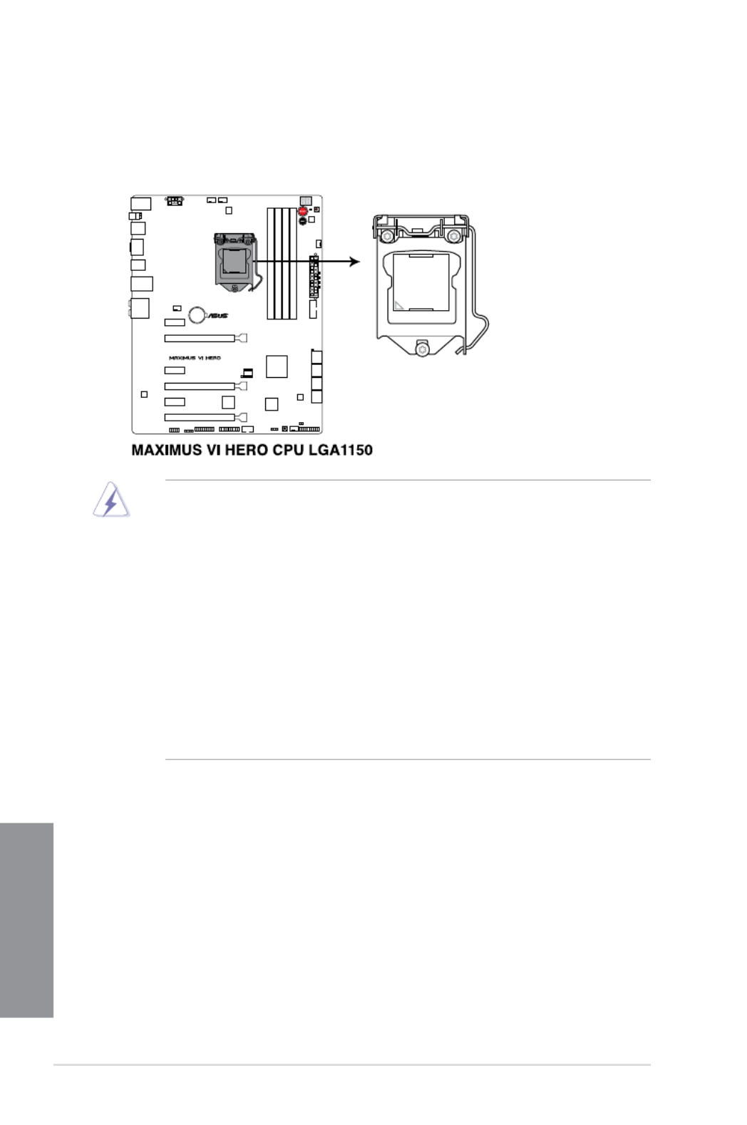
1.2.3 Central Processing Unit (CPU)
The motherboard comes with a surface mount LGA1150 socket designed for the 4th
Generation Intel® Core™ i7 / Intel® Core™ i5 / Intel® Core™ i3, Pentium®, and Celeron®
processors.
• Ensure that all power cables are unplugged before installing the CPU.Ensure that all power cables are unplugged before installing the CPU.
• Ensure that you install the correct CPU designed for LGA1150 only. DO NOT install a
CPU designed for LGA1155 and LGA1156 sockets on the LGA1150 socket.
• Upon purchase of the motherboard, ensure that the PnP cap is on the socket andUpon purchase of the motherboard, ensure that the PnP cap is on the socket and
the socket contacts are not bent. Contact your retailer immediately if the PnP cap
is missing, or if you see any damage to the PnP cap/socket contacts/motherboard
components. ASUS will shoulder the cost of repair only if the damage is shipment/
transit-related.
• Keep the cap after installing the motherboard. ASUS will process Return MerchandiseKeep the cap after installing the motherboard. ASUS will process Return Merchandise
Authorization (RMA) requests only if the motherboard comes with the cap on the
LGA1150 socket.
• The product warranty does not cover damage to the socket contacts resulting fromThe product warranty does not cover damage to the socket contacts resulting from
incorrect CPU installation/removal, or misplacement/loss/incorrect removal of the PnP
cap.

ASUS MAXIMUS VI HERO 1-9
Chapter 1
Recommended memory congurations
1.2.4 System memory
The motherboard comes with four Double Data Rate 3 (DDR3) Dual Inline Memory Modules
(DIMM) slots.
A DDR3 module is notched differently from a DDR or DDR2 module. DO NOT install a DDR
or DDR2 memory module to the DDR3 slot.
1-10 Chapter 1: Product introduction
Chapter 1
Memory congurations
You may install 1GB, 2GB, 4GB and 8GB unbuffered and non-ECC DDR3 DIMMs into the
DIMM sockets.
• Memory module with memory frequency higher than 2133 MHz and its corresponding
timing or the loaded XMP prole is not the JEDEC memory standard. The stability and
compatibility of these memory modules depend on the CPU’s capabilities and other
installed devices.
• You may install varying memory sizes in Channel A and Channel B. The system mapsYou may install varying memory sizes in Channel A and Channel B. The system maps
the total size of the lower-sized channel for the dual-channel conguration. Any excess
memory from the higher-sized channel is then mapped for single-channel operation.
• According to Intel CPU spec, DIMM voltage below 1.65V is recommended to protectAccording to Intel CPU spec, DIMM voltage below 1.65V is recommended to protect
the CPU.
• Always install DIMMs with the same CAS latency. For optimal compatibility, weAlways install DIMMs with the same CAS latency. For optimal compatibility, we
recommend that you install memory modules of the same version or date code (D/C)
from the same vendor. Check with the retailer to get the correct memory modules.
• Due to the memory address limitation on 32-bit Windows OS, when you install 4GBDue to the memory address limitation on 32-bit Windows OS, when you install 4GB
or more memory on the motherboard, the actual usable memory for the OS can be
about 3GB or less. For effective use of memory, we recommend that you do any of the
following:
a) Use a maximum of 3GB system memory if you are using a 32-bit Windows OS.Use a maximum of 3GB system memory if you are using a 32-bit Windows OS.
b) Install a 64-bit Windows OS when you want to install 4GB or more on theInstall a 64-bit Windows OS when you want to install 4GB or more on thenstall a 64-bit Windows OS when you want to install 4GB or more on the
motherboard.
c) For more details, refer to the Microsoft
®
support site at http://support.microsoft.
com/kb/929605/en-us.
• This motherboard does not support DIMMs made up of 512Mb (64MB) chips or less
(Memory chip capacity counts in Megabit, 8 Megabit/Mb = 1 Megabyte/MB).
• The default memory operation frequency is dependent on its Serial Presence DetectThe default memory operation frequency is dependent on its Serial Presence Detect
(SPD), which is the standard way of accessing information from a memory module.
Under the default state, some memory modules for overclocking may operate at a
lower frequency than the vendor-marked value. To operate at the vendor-marked or at
a higher frequency, refer to section 3.4 Extreme Tweaker menu for manual memory
frequency adjustment.
• For system stability, use a more efcient memory cooling system to support a fullFor system stability, use a more efcient memory cooling system to support a full
memory load (4 DIMMs) or overclocking condition.

ASUS MAXIMUS VI HERO 1-11
Chapter 1
MAXIMUS VI HERO Motherboard Qualied Vendors Lists (QVL)
DDR3 2800 MHz capability
DDR3 2600 MHz capability
DDR3 2666 MHz capability
Vendors Part No. Size SS/
DS
Chip
Brand
Chip
NO.
Timing Voltage DIMM
socket
support
(Optional)
2 4
AVEXIR AVD3U28001204G-4CI 16GB ( 4x 4GB ) DS - - 12-14-14-35 1.65V • •
CORSAIR CMD16GX3M4A2800C11 16GB ( 4x 4GB ) DS - - 11-14-14-35 1.65V • •
CORSAIR CMD16GX3M4A2800C12 16GB ( 4x 4GB ) DS - - 12-14-14-36 1.65V • •
G.SKILL F3-2800C11D-8GTXD 8GB ( 2x 4GB ) DS - - 11-13-13-35 1.65V • •
G.SKILL F3-2800C11Q-16GTXD 16GB ( 4x 4GB ) DS - - 11-13-13-35 1.65V • •
G.SKILL F3-2800C11D-8GTXDG 8GB ( 2x 4GB ) DS - - 11-14-14-35 1.65V • •
G.SKILL F3-2800C11Q-16GTXDG 16GB ( 4x 4GB ) DS - - 11-13-13-35 1.65V • •
G.SKILL F3-2800C12Q-32GTXG 32GB (4 x 8GB ) DS - - 12-13-13-35 1.65V • •
G.SKILL F3-2800C10D-8GBTXD 8GB ( 2x 4GB ) DS - - 10-13-13-35 1.65V • •
Vendors Part No. Size SS/
DS
Chip
Brand
Chip
NO.
Timing Voltage DIMM
socket
support
(Optional)
2 4
Apacer 78.BAGFF.AFC0C(XMP) 8GB ( 2x 4GB ) DS - - 12-13-13-35 - • •
Apacer 78.BAGFR.AFD0C(XMP) 8GB ( 2x 4GB ) DS - - 12-13-13-35 - • •
Apacer 78.CAGFF.AFD0C(XMP) 16GB ( 2x 8GB ) DS - - 12-13-13-35 - • •
G.SKILL F3-2666C11Q-32GTXD(XMP) 32GB ( 4x 8GB ) DS - - - 1.65 • •
G.SKILL F3-2666CL10Q-16GBZHD(XMP) 16GB ( 4x 4GB ) DS - - 10-12-12-31 1.65 •
GEIL GOC332GB2666C11QC(XMP) 32GB ( 4x 8GB ) DS - - 11-13-13-32 1.65 • •
Team TXD34G2666HC11CBK(XMP) 8GB ( 2x 4GB ) SS - - 11-13-13-35 1.65 • •
Team TXD38G2666HC11CBK(XMP) 16GB ( 2x 8GB ) DS - - 11-13-13-35 1.65 •
Vendors Part No. Size SS/
DS Chip
Brand Chip
NO. Timing Voltage DIMM
socket
support
(Optional)
2 4
A-DATA AX3U2600GW8G11(XMP) 16GB ( 2x 8GB ) DS - - 11-13-13-35 1.65 • •

1-12 Chapter 1: Product introduction
Chapter 1
DDR3 2500 MHz capability
Vendors Part No. Size SS/
DS
Chip
Brand
Chip
NO.
Timing Voltage DIMM
socket
support
(Optional)
2 4
G.SKILL F3-20000CL10Q-16GBZHD(XMP) 16GB ( 4x 4GB ) DS - - 10-11-11-31 1.65 • •
DDR3 2400 MHz capability
Vendors Part No. Size SS/DS Chip
Brand
Chip
NO.
Timing Voltage DIMM
socket
support
(Optional)
2 4
A-DATA AX3U2400GC4G10(XMP) 4GB DS - - 10-12-12-31 1.65 • •
A-DATA AX3U2400GW8G11(XMP) 16GB ( 2x 8GB ) DS - - 11-13-13-35 1.65 • •
Apacer 78.BAGFL.AFD0C(XMP) 8GB ( 2x 4GB ) DS - - 11-12-12-30 - • •
Apacer 783BAGF3.AFD0C(XMP) 8GB ( 2x 4GB ) DS - - 11-11-11-30 - • •
CORSAIR CMGTX8(XMP) 8GB ( 4x 2GB ) SS - - 10-12-10-30 1.65 • •
CORSAIR CMZ16GX3M2A2400C10
(Ver4.21)
16GB ( 2x 8GB ) DS - - 10-12-12-31 1.65 • •
CORSAIR CMZ16GX3M4A2400C9R
(Ver4.13)(XMP)
16GB ( 4x 4GB ) DS - - 2400 9-11-11-31 1.65 • •
G.SKILL F3-19200CL10Q-
32GBZHD(XMP)
32GB ( 4x 8GB ) DS - - 10-12-12-31 1.65 • •
G.SKILL F3-19200CL11Q-
16GBZHD(XMP)
16GB ( 4x 4GB ) DS - - 11-11-11-31 1.65 • •
G.SKILL F3-19200CL11Q-
16GBZHD(XMP)
16GB ( 4x 4GB ) DS - - 11-11-11-31 1.65 • •
G.SKILL F3-19200CL9D-
4GBPIS(XMP)
4G ( 2x 2G ) DS - - 9-11-9-28 1.65 •
G.SKILL F3-19200CL9Q-
16GBZMD(XMP)
16GB ( 4x 4GB ) DS - - 9-11-11-31 1.65 • •
GEIL GET34GB2400C9DC
(XMP)
4GB ( 2x 2GB ) DS - - 9-11-9-27 1.65 •
GEIL GOC316GB2400C10QC
(XMP)
16GB ( 4x 4GB ) DS - - 10-11-11-30 1.65 • •
GEIL GOC316GB2400C11QC
(XMP)
16GB ( 4x 4GB ) DS - - 11-11-11-30 1.65 • •
Kingston KHX2400C11D3K4/
8GX(XMP) 8GB ( 4x 2GB ) SS - - 11-13-11-30 1.65 • •
KINGSTON KHX24C11K4/16X(XMP) 16GB ( 4x 4GB ) DS - - 11-13-13-30 1.65 • •
KINGSTON KHX24C11T2K2/8X(XMP) 8GB ( 2x 4GB ) DS - - - 1.65 • •
KINGSTON KHX24C11T3K4/32X(XMP) 32GB ( 4x 8GB ) DS - - 9-9-9-24 1.65 • •
Patriot PVV34G2400C9K(XMP) 4GB ( 2x 2GB ) DS - - 9-11-9-27 1.66 •
Patriot PXD38G2400C11K(XMP) 8GB ( 2x 4GB ) DS - - 11-11-11-30 1.65 • •
Patriot PXD38G2400C11K(XMP) 8GB ( 2x 4GB ) DS - - 2400 11-11-11-30 1.65 • •
Team TXD38G2400HC10QBK
(XMP)
8GB DS - - 10-12-12-31 1.65 • •

ASUS MAXIMUS VI HERO 1-13
Chapter 1
DDR3 2200 MHz capability
Vendors Part No. Size SS/
DS
Chip
Brand
Chip
NO.
Timing Voltage DIMM
socket
support
(Optional)
2 4
G.SKILL F3-17600CL7D-4GBFLS(XMP) 4G ( 2x 2G ) DS - - 7-10-10-28 1.65 •
GEIL GET34GB2200C9DC(XMP) 4GB ( 2x 2GB ) DS - - 9-10-9-28 1.65 • •
GEIL GET38GB2200C9ADC(XMP) 8GB ( 2x 4GB ) DS - - 9-11-9-28 1.65 • •
DDR3 2133 MHz capability
Vendors Part No. Size SS/
DS
Chip
Brand
Chip
NO.
Timing Voltage DIMM
socket
support
(Optional)
2 4
A-DATA AX3U2133XC4G10(XMP) 4GB DS - - 10-11-11-30 1.65 • •
A-DATA AX3U2133XW8G10(XMP) 16GB ( 2x 8GB ) DS - - 10-11-11-30 1.65 • •
A-DATA AX3U2133XW8G10(XMP) 8GB DS - - 10-11-11-30 1.65 • •
Apacer 78.BAGE4.AFD0C(XMP) 8GB ( 2x 4GB ) DS - - 9-9-9-24 - • •
Apacer AHU04GFB33CAQ3R(XMP) 4GB DS - - 11-13-13-31 - • •
CORSAIR CMD8GX3M2A2133C9
(Ver1.5)(XMP)
8GB ( 2x 4GB ) DS - - 9-11-10-27 1.5 •
CORSAIR CMT4GX3M2B2133C9(Ver
7.1)(XMP)
4GB ( 2x 2GB ) DS - - 9-10-9-27 1.5 • •
CORSAIR CMT4GX3M2B2133C9(XMP) 4GB ( 2x 2GB ) DS - - 9-10-9-27 1.5 • •
G.SKILL F3-17000CL11Q2-
64GBZLD(XMP)
64GB ( 8x 8GB ) DS - - 11-11-11-30 1.5 • •
G.SKILL F3-17000CL9Q-
16GBXLD(XMP)
16GB ( 4x 4GB ) DS - - 9-11-9-28 1.65 • •
G.SKILL F3-17000CL9Q-
16GBZH(XMP)
16GB ( 4x 4GB ) DS - - 9-11-10-28 1.65 • •
G.SKILL F3-17066CL9D-
8GBPID(XMP)
8GB ( 2x 4GB ) DS - - 9-9-9-24 1.65 • •
G.SKILL F3-17066CL9Q-
16GBTDD(XMP)
16GB ( 4x 4GB ) DS - - 9-9-9-24 1.65 •
G.SKILL F3-2133C11Q-32GZL(XMP) 32GB ( 4x 8GB ) DS - - 11-11-11-31 1.5 • •
KINGSTON KHX2133C11D3K4/
16GX(XMP)
16GB ( 4x 4GB ) DS - - 11-12-11-30 1.65 • •
KINGSTON KHX21C11T3FK8/64X(XMP) 64GB ( 8x 8GB ) DS - - 9-9-9-24 1.5 • •
OCZ OCZ3XTEP2133C9LV4GK 2GB DS - - 7-7-7-20 1.65 •
Patriot PV316G213C1K(XMP) 16GB ( 2x 8GB ) DS - - 11-11-11-30 1.5 • •
Patriot PVV34G2133C9K(XMP) 4GB ( 2x 2GB ) DS - - 9-11-9-27 1.66 • •
Patriot PXD38G2133C11K(XMP) 8GB ( 2x 4GB ) DS - - 9-9-9-24 1.65 •
Patriot PXD38G2133C11K(XMP) 8GB ( 2x 4GB ) DS - - 2133 11-11-
11-27
1.5 • •
Team TLD38G2133HC11ABK
(XMP)
8GB DS - - 11-11-11-31 1.65 • •
Team TXD34096M2133HC11A-
V(XMP)
4GB DS - - 11-11-11-31 1.65 • •

1-14 Chapter 1: Product introduction
Chapter 1
DDR3 2000 MHz capability
Vendors Part No. Size SS/
DS
Chip
Brand
Chip NO. Timing Voltage DIMM
socket
support
(Optional)
2 4
AEXEA AXA3ES2G2000LG28V
(XMP)
2GB DS - - - 1.65 • •
AEXEA AXA3ES4GK2000LG28V
(XMP)
4GB ( 2x 2GB ) DS - - - 1.65 • •
Apacer 78.AAGD5.9KD (XMP) 6GB ( 3x 2GB ) DS - - 9-9-9-27 - • •
Asint SLA302G08-ML2HB
(XMP)
4GB DS Hynix H5TQ2G83BFRH9C 9-9-9-27 - • •
G.SKILL F3-16000CL9D-4GBRH
(XMP)
4GB ( 2x 2GB ) DS - - 9-9-9-24 1.65 •
G.SKILL F3-16000CL9D-4GBTD
(XMP)
4GB ( 2x 2GB ) DS - - 9-9-9-24 1.65 •
GEIL GUP34GB2000C9DC
(XMP)
4GB ( 2x 2GB ) DS - - 9-9-9-28 1.65 • •
Patriot PV736G2000ELK (XMP) 6GB ( 3x 2GB ) DS - - 7-7-7-20 1.65 • •
Patriot PVT36G2000LLK (XMP) 6GB ( 3x 2GB ) DS - - 8-8-8-24 1.65 • •
Patriot PX7312G2000ELK
(XMP)
12GB ( 3x 4GB ) DS - - 9-11-
9-27
1.65 • •
Silicon
Power
SP002GBLYU200S02
(XMP)
2GB DS - - - - • •
Team TXD32048M2000C9
(XMP)
2GB DS Team T3D1288RT-20 9-9-9-24 1.5 • •
Team TXD32048M2000C9-L
(XMP)
2GB DS Team T3D1288LT-20 9-9-9-24 1.5 • •
Team TXD32048M2000C9-L
(XMP) 2GB DS Team T3D1288RT-20 9-9-9-24 1.6 • •
ASUS MAXIMUS VI HERO 1-15
Chapter 1
DDR3 1866 MHz capability
Vendors Part No. Size SS/
DS
Chip
Brand
Chip
NO.
Timing Voltage DIMM
socket
support
(Optional)
2 4
A-DATA AX3U1866XW8G10(XMP) 16GB ( 2x 8GB ) DS - - 10-11-10-30 1.5 • •
CORSAIR CMD16GX3M2A1866C9
(Ver5.29)(XMP)
16GB ( 2x 8GB ) DS - - 1866 9-9-9-27 1.5 •
CORSAIR CMD16GX3M4A1866C9
(Ver4.13)(XMP)
16GB ( 4x 4GB ) DS - - 9-10-9-27 1.5 • •
CORSAIR CMD16GX3M4A1866C9
(Ver8.16)(XMP)
16GB ( 4x 4GB ) DS - - 9-10-9-27 1.5 • •
CORSAIR CMD8GX3M2A1866C9
(Ver4.13)(XMP)
8GB ( 2x 4GB ) DS - - - 1.5 • •
CORSAIR CMD8GX3M2A1866C9
(Ver5.12)(XMP)
8GB ( 2x 4GB ) DS - - 9-10-9-27 1.5 •
CORSAIR CMD8GX3M2A1866C9
(Ver8.16)(XMP)
8GB ( 2x 4GB ) DS - - 9-10-9-27 1.5 •
CORSAIR CMT32GX3M4X1866C9(Ver3
.23)(XMP)
32GB ( 4x 8GB ) DS - - 9-10-9-27 1.5 • •
CORSAIR CMZ16GX3M4X1866C9R
(Ver8.16)(XMP) 16GB ( 4x 4GB ) DS - - 9-10-9-27 1.5 • •
CORSAIR CMZ16GX3M4X1866C9R(Ver
8.16)(XMP) 16GB ( 4x 4GB ) DS - - 9-10-9-27 1.5 • •
CORSAIR CMZ32GX3M4X1866C10
(Ver3.23)(XMP)
32GB ( 4x 8GB ) DS - - 10-11-10-27 1.5 • •
CORSAIR CMZ32GX3M4X1866C10(Ver
3.23)(XMP)
32GB ( 4x 8GB ) DS - - 10-11-10-27 1.5 • •
CORSAIR CMZ8GX3M2A1866C9
(Ver8.16)(XMP)
8GB ( 2x 4GB ) DS - - 9-10-9-27 1.5 • •
CORSAIR CMZ8GX3M2A1866C9(XMP) 8GB ( 2x 4GB ) DS - - 9-10-9-27 1.5 •
CORSAIR CMZ8GX3M2A1866C9G
(Ver5.12)(XMP)
8GB ( 2x 4GB ) DS - - 1866 9-10-
9-27
1.5 • •
Crucial BLE4G3D1869DE1XT0.16F
MD(XMP)
4GB DS - - 9-9-9-27 1.5 • •
G.SKILL F3-14900CL10Q2-
64GBZLD(XMP)
64GB ( 8x 8GB ) DS - - 10-11-10-30 1.5 • •
G.SKILL F3-14900CL9D-8GBSR(XMP) 8GB ( 2x 4GB ) DS - - 9-10-9-28 1.5 • •
G.SKILL F3-14900CL9Q-16GBXL(XMP) 16GB ( 4x 4GB ) DS - - 9-10-9-28 1.5 • •
G.SKILL F3-14900CL9Q-16GBZL(XMP) 16GB ( 4x 4GB ) DS - - 9-10-9-28 1.5 • •
G.SKILL F3-14900CL9Q-8GBFLD(XMP) 8GB ( 2x 4GB ) DS - - 9-9-9-24 1.6 • •
G.SKILL F3-1866C9Q-32GXM(XMP) 32GB ( 4x 8GB ) DS - - 9-10-9-28 1.5 • •
KINGSTON KHX1866C9D3K2/8GX(XMP) 8GB ( 2x 4GB ) DS - - - 1.65 • •
Patriot PXD34G1866ELK(XMP) 4GB ( 2x 2GB ) SS - - 9-9-9-24 1.65 • •
Patriot PXD38G1866ELK(XMP) 8GB ( 2x 4GB ) DS - - 9-11-9-27 1.65 • •
Patriot PXD38G1866ELK(XMP) 8GB ( 2x 4GB ) DS - - 9-11-9-27 1.65 • •
Patriot PXD38G1866ELK(XMP) 8GB ( 2x 4GB ) DS - - 1866 9-10-
9-27
1.5 • •
Team TED34G1866HC13BK 4GB SS - - - - • •
Team TED38G1866HC-13BK 8GB DS - - - - • •
Team TLD34G1866HC9KBK(XMP) 4GB DS - - 9-11-9-27 1.5 • •
Team TLD38G1866HC10SBK(XMP) 8GB DS - - 10-11-10-30 1.5 • •

1-16 Chapter 1: Product introduction
Chapter 1
DDR3 1800 MHz capability
Vendors Part No. Size SS/
DS
Chip
Brand
Chip
NO.
Timing Voltage DIMM
socket
support
(Optional)
2 4
G.SKILL F3-14400CL9D-4GBRL(XMP) 4GB ( 2x 2GB ) DS - - 9-9-9-24 1.65 • •
DDR3 1600 MHz capability
(continued on the next page)
Vendors Part No. Size SS/
DS
Chip
Brand
Chip NO. Timing Voltage DIMM
socket
support
(Optional)
2 4
A-DATA AD3U1600C2G11 2GB SS MICRON D9PFJ 11-11-11-28 - • •
A-DATA AD3U1600C4G11 4GB DS MICRON D9PFJ 11-11-11-28 - • •
A-DATA AD3U1600W4G11 4GB SS A-DATA 3WCD-1211A 11-11-11-28 - • •
A-DATA AD3U1600W8G11 8GB DS A-DATA 3WCD-1211A 11-11-11-28 - • •
A-DATA AX3U1600GW8G9
(XMP)
16GB
(2x8GB )
DS - - 9-9-9-24 1.5 • •
A-DATA AX3U1600W8G11 16GB
(2x8GB )
DS - - 9-11-9-27 1.5 • •
A-DATA AXDU1600GW8G9B
(XMP)
16GB
(2x8GB )
DS - - 9-11-9-27 1.65 • •
AMD AE32G1609U1-U 2GB SS AMD 23EY4587MB6H - 1.5 • •
AMD AE34G1609U2-U 4GB DS AMD 23EY4587MB6H - 1.5 • •
AMD AP38G1608U2K
(XMP)
8GB
(2x4GB )
DS - - 9-9-9-28 1.65 • •
Apacer 78.B1GE3.9L10C 4GB DS Apacer AM5D5908DEQSCK - 1.65 • •
Apacer 78.B1GET.9K00C 4GB SS Apacer AM5D6008BQQSCK 11-11-11-28 - • •
Apacer 78.C1GET.9K10C 8GB DS Apacer AM5D6008BQQSCK 11-11-11-31 - • •
Apacer AHU04GFA60C9Q3R
(XMP)
4GB DS - - 11-11-11-28 - • •
Apacer AHU08GFA60CBT3R
(XMP)
8GB DS - - 9-9-9-24 - • •
Asint SLA302G08-EGG1C
(XMP)
4GB DS Asint 302G08-GG1C 9-9-9-27 - • •
Asint SLA302G08-EGJ1C
(XMP)
4GB DS Asint 302G08-GJ1C 9-9-9-27 - • •
Asint SLA302G08-EGN1C 4GB DS ASint 302G08-GN1C - - • •
Asint SLA304G08-ENG1B 4GB SS Asint 304G08-GN1B 9-11-11-28 - • •
Asint SLB304G08-EGJ1B
(XMP)
8GB DS - - 9-9-9-27 - • •
Asint SLB304G08-EGN1B 8GB DS ASint 304G08-GN1B - - • •
Asint SLZ302G08-EGN1C 2GB SS ASint 302G08-GN1C - - • •
Asint SLZ3128M8-
EGJ1D(XMP)
2GB DS Asint 3128M8-GJ1D - - • •
ATP AQ12M64B8BKK0S 4GB DS SAMSUNG K4B2G08460 - NO • •

ASUS MAXIMUS VI HERO 1-17
Chapter 1
DDR3 1600 MHz capability
Vendors Part No. Size SS/
DS
Chip
Brand
Chip NO. Timing Voltage DIMM
socket
support
(Optional)
2 4
CORSAIR CMD16GX3M2A1600C9
(Ver8.21)(XMP)
16GB
(2x8GB )
DS - - 9-9-9-24 1.5 •
CORSAIR CMD8GX3M2A1600C8
(Ver5.12)(XMP)
8GB
(2x4GB )
DS - - 1600 8-8-
8-24
1.5 • •
CORSAIR CMD8GX3M2A1600C9
(Ver2.12)(XMP)
8GB
(2x4GB )
DS - - 9-9-9-24 1.5 • •
CORSAIR CMG4GX3M2A1600C6 4GB
(2x2GB )
DS - - 6-6-6-18 1.65 • •
CORSAIR CML16GX3M4X1600C8
(Ver 2.12)(XMP)
16GB
(4x4GB )
DS - - Heat-Sink
Package
1.5 • •
CORSAIR CMP6GX3M3A1600C8
(XMP)
6GB
(3x2GB )
DS - - 8-8-8-24 1.65 • •
CORSAIR CMP6GX3M3A1600C8
(XMP)
6GB
(3x2GB )
DS - - 8-8-8-24 1.65 • •
CORSAIR CMX6GX3M3C1600C7
(XMP)
6GB
(3x2GB )
DS - - 7-8-7-20 1.65 • •
CORSAIR CMX8GX3M2A1600C9
(Ver3.19)(XMP) 8GB
(2x4GB ) SS - - 9-9-9-24 1.65 • •
CORSAIR CMZ16GX3M2A1600C10
(Ver.3.24)(XMP) 16GB
(2x8GB ) DS - - 10-10-10-27 1.5 • •
CORSAIR CMZ16GX3M4A1600C9
(XMP) 16GB
(4x4GB ) DS - - 9-9-9-24 1.5 • •
CORSAIR CMZ32GX3M4X1600C10
(Ver2.2)(XMP)
32GB
(4x8GB )
DS - - 10-10-10-27 1.5 • •
CORSAIR CMZ8GX3M2A1600C8
(XMP)
8GB
(2x4GB )
DS - - 8-8-8-24 1.5 • •
CORSAIR CMZ8GX3M4X1600C9
(Ver 2.12)(XMP)
8GB
(4x2GB )
SS - - 9-9-9-24 1.5 • •
CORSAIR HX3X12G1600C9 (XMP) 12GB
(6x2GB )
DS - - 9-9-9-24 1.6 • •
Crucial BL12864BN1608.8FF
(XMP)
2GB
(2x1GB )
SS - - 8-8-8-24 1.65 • •
Crucial BLT4G3D1608DT1TX
0.16FM (XMP)
4GB DS - - 8-8-8-24 1.5 • •
EK
Memory
EKM324L28BP8-I16
(XMP)
4GB
(2x2GB )
DS - - 9 - • •
EK
Memory
EKM324L28BP8-I16
(XMP)
4GB
(2x2GB )
DS - - 9 - • •
Elixir M2X2G64CB88G7N-DG
(XMP)
2GB SS Elixir N2CB2G80GN-DG 9-9-9-28 - • •
Elixir M2X4G64CB8HG5N-DG
(XMP)
4GB DS Elixir N2CB2G80GN-DG 9-9-9-28 - • •
Elixir M2X8G64CB8HB5N-DG
(XMP)
8GB DS Elixir N2CB4G80BN-DG 9-9-9-28 1.5 • •
G.SKILL F3-12800CL7D-8GBRH
(XMP)
8GB
(2x4GB )
DS - - 7-8-7-24 1.6 • •
G.SKILL F3-12800CL7Q-16GBXH
(XMP)
16GB
(4x4GB )
DS - - 7-8-7-24 1.6 • •
G.SKILL F3-12800CL8D-
8GBECO (XMP)
8GB
(2x4GB )
DS - - 8-8-8-24 1.35 •
(continued on the next page)

1-18 Chapter 1: Product introduction
Chapter 1
(continued on the next page)
DDR3 1600 MHz capability
Vendors Part No. Size SS/
DS
Chip
Brand
Chip NO. Timing Voltage DIMM
socket
support
(Optional)
2 4
G.SKILL F3-12800CL9D-
8GBRL (XMP)
8GB
(2x4GB )
DS - - 9-9-9-24 1.5 • •
G.SKILL F3-12800CL9D-
8GBSR2 (XMP)
8GB
(2x4GB )
DS - - 9-9-9-24 1.25 • •
G.SKILL F3-12800CL9Q-
16GBXL (XMP)
16GB
(4x4GB )
DS - - 9-9-9-24 1.5 • •
G.Skill F3-12800CL9Q-
16GBZL (XMP)
16GB
(4x4GB )
DS - - 9-9-9-24 1.5 • •
G.SKILL F3-1600C9Q-32GXM
(XMP)
32GB
(4x8GB )
DS - - - 1.5 • •
GEIL GET316GB1600C9QC
(XMP)
16GB
(4x4GB )
DS - - 9-9-9-28 1.6 • •
GEIL GUP34GB1600C7DC
(XMP)
4GB
(2x2GB )
DS - - 7-7-7-24 1.6 • •
GoodRam GR1600D364L9/2G 2GB DS GoodRam GF1008KC-JN - - • •
KINGMAX FLGE85F-C8KL9A
(XMP)
2GB SS KINGMAX N/A 9-9-9-28 - • •
KINGMAX FLGF65F-C8KL9A
(XMP)
4GB DS KINGMAX N/A 9-9-9-28 - • •
KINGSTON KHX16009CD3K2/
8GX(XMP)
8GB
(2x4GB )
DS - - 9-9-9-27 1.65 • •
KINGSTON KHX1600C9D3B1/4G
(XMP) 4GB SS - - 9-9-9-27 1.65 • •
KINGSTON KHX1600C9D3K3/
12GX (XMP) 12GB
(3x4GB ) DS - - 9 1.65 • •
KINGSTON KHX1600C9D3K3/
6GX(XMP)
6GB
(3x2GB )
DS - - 9 1.65 • •
KINGSTON KHX1600C9D3K3/
6GX(XMP)
6GB
(3x2GB )
DS - - 9 1.65 • •
KINGSTON KHX1600C9D3K4/
16GX(XMP)
16GB
(4x4GB )
DS - - 9-9-9-24 1.65 • •
KINGSTON KHX1600C9D3K6/
24GX(XMP)
24GB
(6x4GB )
DS - - 9 1.65 • •
KINGSTON KHX1600C9D3K8/
32GX(XMP)
32GB
(8x4GB )
DS - - 9-9-9-27 1.65 • •
KINGSTON KHX1600C9D3LK2/
8GX(XMP)
8GB
(2x4GB )
DS - - 9-9-9-24 1.35 • •
KINGSTON KHX1600C9D3P1K2/
8G
8GB
(2x4GB )
DS - - 9 1.5 • •
KINGSTON KHX16C10B1K2/
16X(XMP)
16GB
(2x8GB )
DS - - - 1.5 • •
KINGSTON KHX16C9K2/16 16GB
( 2x
8GB )
DS - - 1333-9-9-
9-24
1.5 • •
KINGSTON KHX16C9P1K2/16 16GB
(2x8GB )
DS - - - 1.5 • •
KINGSTON KVR16N11/4 4G DS Hynix H5TQ2G83CFRPBC - 1.5 • •
KINGTIGER KTG2G1600PG3
(XMP)
2GB DS - - - - • •
MICRON MT16JTF1G64AZ-
1G6D1
8GB DS MICRON D9PBC - 1.5 • •
ASUS MAXIMUS VI HERO 1-21
Chapter 1
(continued on the next page)
DDR3 1333 MHz capability
Vendors Part No. Size SS/
DS
Chip Brand Chip NO. Timing Voltage DIMM
socket
support
(Optional)
2 4
GEIL GG34GB1333C9DC 4GB
(2x2GB)
DS GEIL GL1L128M88BA115FW 9-9-9-24 1.3 • •
GEIL GG34GB1333C9DC 4GB
(2x2GB)
DS GEIL GL1L128M88BA15B 9-9-9-24 1.3 • •
GEIL GVP34GB1333C9DC 4GB
(2x2GB)
DS - - 9-9-9-24 1.5 • •
GEIL GVP38GB1333C7QC 8GB
(4x2GB)
DS - - 7-7-7-24 1.5 • •
GEIL GVP38GB1333C9DC 8GB
(2x4GB) DS - - 9-9-9-24 1.5 • •
GoodRam GR1333D364L9/2G 2GB DS Qimonda IDSH1G-03A1F1C-
13H - - • •
Hynix HMT125U6TFR8A-H9 2GB DS Hynix H5TC1G83TFR - - • •
INNODISK M3UN-2GHJBC09 2GB SS Hynix H5TQ2G83CFRH9C 9-9-9-24 - • •
INNODISK M3UN-4GHJAC09 4GB DS Hynix H5TQ2G83CFRH9C 9-9-9-24 - • •
KINGMAX FLFE85F-B8KL9 2GB DS KINGMAX KFB8FNLXL-BNF-15A - - • •
KINGMAX FLFE85F-C8KL9 2GB SS KINGMAX KFC8FNLBF-GXX-12A - - • •
KINGMAX FLFE85F-C8KL9 2GB SS KINGMAX KFC8FNLXF-DXX-15A - - • •
KINGMAX FLFE85F-C8KM9 2GB SS Kingmax KFC8FNMXF-
BXX-15A
- - • •
KINGMAX FLFF65F-C8KL9 4GB DS KINGMAX KFC8FNLXF-DXX-15A - - • •
KINGMAX FLFF65F-C8KM9 4GB DS Kingmax KFC8FNMXF-
BXX-15A
- - • •
KINGSTON KVR1333D3E9S/4G 4GB DS Elpida J2108ECSE-DJ-F 9 1.5 • •
KINGSTON KVR1333D3N9H/4G 4GB DS ELPIDA J2108BDBG-GN-F - 1.5 • •
KINGSTON KVR1333D3N9H/8G 8GB DS ELPIDA J4208EASE-DJ-F 9-9-9-24 1.5 • •
KINGSTON KVR13N9S8H/4 4GB SS ELPIDA J4208BBBG-GN-F - 1.5 • •
KINGTIGER F10DA2T1680 2GB DS KINGTIGER KTG1333PS1208NST-
C9
- - • •
KINGTIGER KTG2G1333PG3 2GB DS - - - - • •
Mach
Xtreme
MXD3U133316GQ 16GB
(4x4GB)
DS - - - - • •
Mach
Xtreme
MXD3V13332GS 2GB SS Mach
Xtreme
C2S46D30-D313 - - • •
MICRON MT8JTF25664AZ-1G4M1 2GB SS MICRON D9PFJ - - • •
OCZ OCZ3G1333LV4GK 4GB
(2x2GB)
DS - - 9-9-9 1.65 •
OCZ OCZ3G1333LV8GK 8GB
(2x4GB)
DS - - 9-9-9 1.65 •
OCZ OCZ3G1333LV8GK 8GB
(2x4GB)
DS - - 9-9-9 1.65 •
OCZ OCZ3RPR1333C9LV8GK 8GB
(2x4GB)
DS - - 9-9-9 1.65 •
Patriot PG38G1333EL(XMP) 8GB DS - - - 1.5 • •

1-22 Chapter 1: Product introduction
Chapter 1
DDR3 1333 MHz capability
Vendors Part No. Size SS/
DS
Chip Brand Chip NO. Timing Voltage DIMM
socket
support
(Optional)
2 4
Patriot PGD316G1333ELK
(XMP)
16GB
(2x8GB)
DS - - 9-9-9-24 1.5 • •
Patriot PSD32G13332 2GB DS Prtriot PM128M8D3BU-15 9 - • •
RiDATA C304627CB1AG22Fe 2GB DS RiDATA C304627CB1AG22Fe 9 - • •
RiDATA E304459CB1AG32Cf 4GB DS RiDATA E304459CB1AG32Cf 9 - • •
SAMSUNG M378B5273CH0-CH9 4GB DS SAMSUNG K4B2G0846C - - • •
Silicon
Power
SP001GBLTE133S01 1GB SS NANYA NT5CB128M8AN-CG - - • •
Silicon
Power
SP001GBLTU133S02 1GB SS S-POWER 10YT3E5 9 - • •
Silicon
Power
SP002GBLTU133V02 2GB SS S-POWER 20YT3NG 9-9-9-24 - • •
Silicon
Power
SP004GBLTU133V02 4GB DS S-POWER 20YT3NG 9-9-9-24 - • •
Team TED34096M1333HC9 4GB DS Team T3D2568LT-13 - - • •
Transcend JM1333KLH-8G(623654) 8GB DS Transcend TK963EBF3 - - • •
Transcend TS1GLK64V3H(620053) 8GB DS MICRON D9QBJ - - • •
Side(s): SS - Single-sided DS - Double-sided DIMM support:
(1) Supports one (1) module inserted into any slot as Single-channel memory
conguration. We suggest that you install the module into A1 slot.
(2) Supports two (2) modules inserted into either the red slots or the black slots as one
pair of Dual-channel memory conguration. We suggest that you install the modules
into slots A1 and B1 for better compatibility.
(4) Supports four (4) modules inserted into both the red and black slots as two pairs of
Dual-channel memory conguration.
• ASUS exclusively provides hyper DIMM support function.
• Hyper DIMM support is subject to the physical characteristics of individual CPUs. LoadHyper DIMM support is subject to the physical characteristics of individual CPUs. Load
the X.M.P. settings in the BIOS for the hyper DIMM support.
• Visit the ASUS website for the latest QVL.Visit the ASUS website for the latest QVL.
ASUS MAXIMUS VI HERO 1-23
Chapter 1
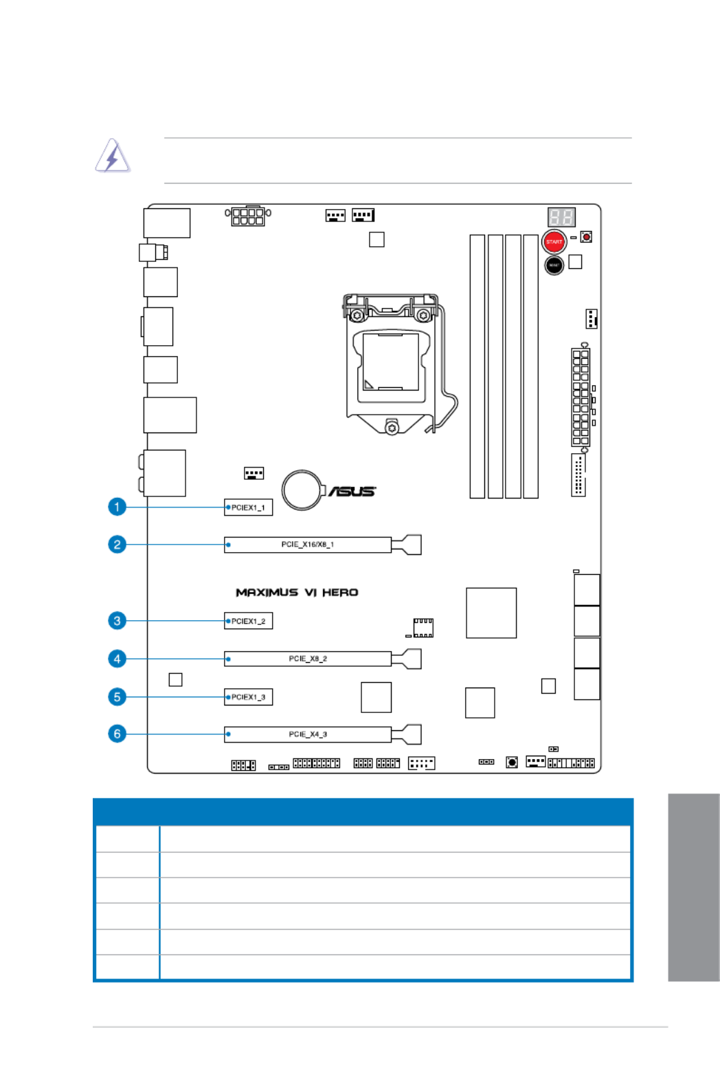
1.2.5 Expansion slots
Unplug the power cord before adding or removing expansion cards. Failure to do so may
cause you physical injury and damage motherboard components.
Slot No. Slot Description
1 PCIe 2.0 x1_1 slot
2 PCIe 3.0/2.0 x16/x8_1 slot
3 PCIe 2.0 x1_2 slot
4 PCIe 3.0/2.0 x16/x8_2 slot
5 PCIe 2.0 x1_3 slot
6 PCIe 2.0 x4_3 slot

1-24 Chapter 1: Product introduction
Chapter 1
• We recommend that you provide sufcient power when running CrossFireX or SLIWe recommend that you provide sufcient power when running CrossFireX or SLI ®
mode.
• Connect a chassis fan to the motherboard connector labeled CHA_FAN1-3 whenConnect a chassis fan to the motherboard connector labeled CHA_FAN1-3 when
using multiple graphics cards for better thermal environment.
• 4th generation Intel4th generation Intel
® Core™ processors support PCIe 3.0 speed rate.
PCIe_x16/x8_1 slot switches to p38-x8 mode when PCIe_x8_2 slots are occupied.
PCIe operating mode
PCIE_x4_3_SPEED PCIE_x1_1 PCIE_x1_2 PCIE_x1_3 PCIE_x4_3
x1 (default) x1 x1 x1 x1
x4 Disabled Disabled Disabled x4
IRQ assignments for this motherboard
A B C D E F G H
PCIE_x16/x8_1 shared – – – – – – –
PCIE_x8_2 – shared – – – – – –
PCIE_x4_3 shared – – – – – – –
PCIE_x1_1 – shared – – – – – –
PCIE_x1_2 – – shared – – – – –
PCIE_x1_3 – – – shared – – – –
I.G.F.X. shared – – – – – – –
Intel LAN Controller – – – – shared – – –
SATA #0 – shared – – – – – –
SATA #1 – shared – – – – – –
High Denition Audio – – – – – – shared –
EHCI# 0 (USB 2.0) – – – – – – shared
EHCI# 1 (USB 2.0) – – – – shared – – –
XHCI (USB 3.0) – – – – – shared – –
Asmedia SATA 6G
Storage Controller – – – shared – – – –
VGA Conguration
PCIe operating mode
PCIE_x16/x8_1 PCIE_x8_2
Single VGA/PCIe card x16
(Recommend for single VGA) N/A
Dual VGA/PCIe card x8 x8
For the PCI Express x4_3 slot (black) bandwidth option, refer to section 3.6.7 Onboard
Devices Conguration.
1-26 Chapter 1: Product introduction
Chapter 1
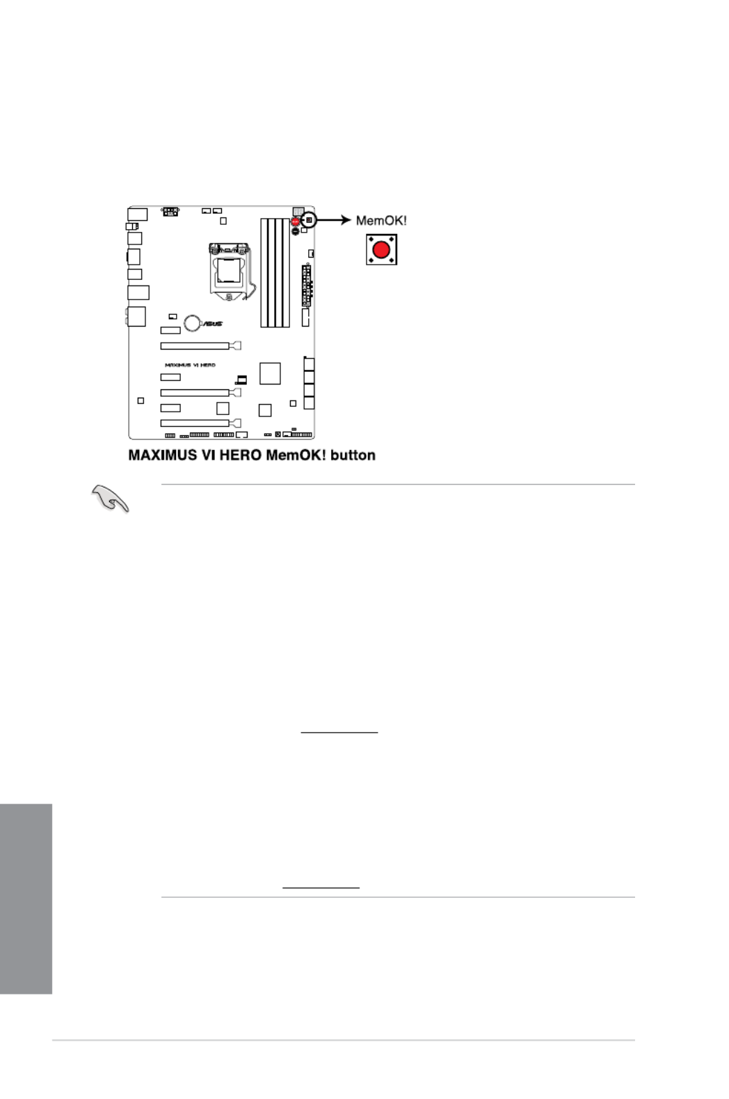
• Refer to section for the exact location of the MEMOK_LED.1.2.8 Onboard LEDs
• The DRAM_LED also lights up when the DIMM is not properly installed. Turn off the
system and reinstall the DIMM before using the MemOK! function.
• The MemOK! button does not function under Windows ® OS environment.
• During the tuning process, the system loads and tests failsafe memory settings. It
takes about 30 seconds for the system to test one set of failsafe settings. If the test
fails, the system reboots and test the next set of failsafe settings. The blinking speed
of the MEMOK_LED increases, indicating different test processes.
• Due to memory tuning requirement, the system automatically reboots when each
timing set is tested. If the installed DIMMs still fail to boot after the whole tuning
process, the DRAM_LED lights continuously. Replace the DIMMs with ones
recommended in the Memory QVL (Qualied Vendors Lists) in this user manual or on
the ASUS website at www.asus.com.
• If you turn off the computer and replace DIMMs during the tuning process, the system
continues memory tuning after turning on the computer. To stop memory tuning, turn
off the computer and unplug the power cord for about 5–10 seconds.
• If your system fails to boot up due to BIOS overclocking, press the MemOK! button
to boot and load the BIOS default settings. A message will appear during POST
reminding you that the BIOS has been restored to its default settings.
• We recommend that you download and update to the latest BIOS version from the
ASUS website at www.asus.com after using the MemOK! function.
3. MemOK! button
Installing DIMMs that are not compatible with the motherboard may cause system
boot failure, and the DRAM_LED near the MemOK! button lights continuously. Press
the MemOK! button until the MEMOK_LED memory compatibility tuning for successful
boot.

ASUS MAXIMUS VI HERO 1-27
Chapter 1
4. DirectKey button
This feature allows your system to go to the BIOS Setup program with the press of
a button. With DirectKey, you can enter the BIOS anytime without having to press
the <Del> key during POST. It also allows you to turn on or turn off your system and
conveniently enter the BIOS during boot-up.
Ensure to save your data before using the DirectKey button.
• When the system is on and you press the DirectKey button, your system will shut
down. Press the DirectKey button again or the Power-on button to reboot and enter
the BIOS directly.
• Turn off your system using the power-on button to allow your system to go through
POST (without entering the BIOS) when you reboot your system.
• Refer to section for details about setting the DirectKey default 3.8 Boot Menu
function.

1-28 Chapter 1: Product introduction
Chapter 1
Except when clearing the RTC RAM, never remove the cap on CLRTC jumper default
position. Removing the cap will cause system boot failure!
To erase the RTC RAM:
1. Turn OFF the computer and unplug the power cord.
2. Move the jumper cap from pins 1-2 (default) to pins 2-3. Keep the cap on pins 2-3 for
about 5-10 seconds, then move the cap back to pins 1-2.
3. Plug the power cord and turn ON the computer.
4. Hold down the key during the boot process and enter BIOS setup to re-enter <Del>
data.
• If the steps above do not help, remove the onboard battery and move the jumper
again to clear the CMOS RTC RAM data. After the CMOS clearance, reinstall the
battery.
• You do not need to clear the RTC when the system hangs due to overclocking. For
system failure due to overclocking, use the C.P.R. (CPU Parameter Recall) feature.
Shut down and reboot the system so the BIOS can automatically reset parameter
settings to default values.
• Due to the chipset behavior, AC power off is required to enable C.P.R. function. You
must turn off and on the power supply or unplug and plug the power cord before
rebooting the system.
1.2.7 Jumper
Clear RTC RAM (3-pin CLRTC)
This jumper allows you to clear the Real Time Clock (RTC) RAM in CMOS. You can clear the
CMOS memory of date, time, and system setup parameters by erasing the CMOS RTC RAM
data. The onboard button cell battery powers the RAM data in CMOS, which include system
setup information such as system passwords.

ASUS MAXIMUS VI HERO 1-29
Chapter 1
1.2.8 Onboard LEDs
1. Hard Disk LED
The hard disk LED is designed to indicate the hard disk activity. It blinks when data
is being written into or read from the hard disk drive. The LED does not light up when
there is no hard disk drive connected to the motherboard or when the hard disk drive
does not function.
2. MemOK! LED
Blinking: Indicates that MemOK! is enabled before POST.

ASUS MAXIMUS VI HERO 1-35
Chapter 1
Code Description
F9 Recovery capsule is not found
FA Invalid recovery capsule
FB – FF Reserved for future AMI error codes
60 DXE Core is started
61 NVRAM initialization
62 Installation of the PCH Runtime Services
63 – 67 CPU DXE initialization is started
68 PCI host bridge initialization
69 System Agent DXE initialization is started
6A System Agent DXE SMM initialization is started
6B – 6F System Agent DXE initialization (System Agent module specic)
70 PCH DXE initialization is started
71 PCH DXE SMM initialization is started
72 PCH devices initialization
73 – 77 PCH DXE Initialization (PCH module specic)
78 ACPI module initialization
79 CSM initialization
7A – 7F Reserved for future AMI DXE codes
90 Boot Device Selection (BDS) phase is started
91 Driver connecting is started
92 PCI Bus initialization is started
93 PCI Bus Hot Plug Controller Initialization
94 PCI Bus Enumeration
95 PCI Bus Request Resources
96 PCI Bus Assign Resources
97 Console Output devices connect
98 Console input devices connect
99 Super IO Initialization
9A USB initialization is started
9B USB Reset
(continued on the next page)
Q-Code table
1-36 Chapter 1: Product introduction
Chapter 1
Code Description
9C USB Detect
9D USB Enable
9E – 9F Reserved for future AMI codes
A0 IDE initialization is started
A1 IDE Reset
A2 IDE Detect
A3 IDE Enable
A4 SCSI initialization is started
A5 SCSI Reset
A6 SCSI Detect
A7 SCSI Enable
A8 Setup Verifying Password
A9 Start of Setup
AA Reserved for ASL (see ASL Status Codes section below)
AB Setup Input Wait
AC Reserved for ASL (see ASL Status Codes section below)
AD Ready To Boot event
AE Legacy Boot event
AF Exit Boot Services event
B0 Runtime Set Virtual Address MAP Begin
B1 Runtime Set Virtual Address MAP End
B2 Legacy Option ROM Initialization
B3 System Reset
B4 USB hot plug
B5 PCI bus hot plug
B6 Clean-up of NVRAM
B7 Conguration Reset (reset of NVRAM settings)
B8– BF Reserved for future AMI codes
D0 CPU initialization error
D1 System Agent initialization error
(continued on the next page)
Q-Code table

1-38 Chapter 1: Product introduction
Chapter 1
1.2.9 Internal connectors
1. Intel ® Z87 Serial ATA 6 Gb/s connectors (7-pin SATA6G_1-6 [red])
These connectors connect to Serial ATA 6 Gb/s hard disk drives via Serial ATA 6 Gb/s
signal cables.
If you installed Serial ATA hard disk drives, you can create a RAID 0, 1, 5, and 10
conguration with the Intel ® Rapid Storage Technology through the onboard Intel ® Z87
chipset.
• These connectors are set to [These connectors are set to [ ] by default. If you intend to create a Serial AHCI Mode
ATA RAID set using these connectors, set the SATA Mode item in the BIOS to [RAID
Mode]. Refer to section 3.6.3 SATA Conguration for details.
• Before creating a RAID set, refer to sectionBefore creating a RAID set, refer to section or the manual 5.1 RAID congurations
bundled in the motherboard support DVD.
• When using NCQ, set the SATA Mode in the BIOS to [When using NCQ, set the SATA Mode in the BIOS to [ ]. Refer to section AHCI Mode
3.6.3 SATA Conguration for details.

ASUS MAXIMUS VI HERO 1-41
Chapter 1
Never connect a 1394 cable to the USB connectors. Doing so will damage the
motherboard!
You can connect the front panel USB cable to the ASUS Q-Connector (USB) rst, and then
install the Q-Connector (USB) to the USB connector onboard if your chassis supports front
panel USB ports.
6. USB 2.0 connectors (10-1 pin USB1112; USB1314)
These connectors are for USB 2.0 ports. Connect the USB module cable to any of
these connectors, then install the module to a slot opening at the back of the system
chassis. These USB connectors comply with USB 2.0 specication that supports up to
480 MBps connection speed.
2 x USB2.0 ports (USB1314) at mid-board shares with ROG extension (ROG_EXT) port.

ASUS MAXIMUS VI HERO 1-45
Chapter 1
10. DirectKey connector (2-pin DRCT)
This connector is for the chassis-mounted button that supports the DirectKey function.
Connect the button cable that supports DirectKey, from the chassis to this connector on
the motherboard.
Ensure that your chassis comes with the extra button cable that supports the DirectKey
feature. Refer to the technical documentation that came with the chassis for details.
Specyfikacje produktu
| Marka: | Asus |
| Kategoria: | płyta główna |
| Model: | MAXIMUS VI HERO |
| Rodzaj zasilania: | ATX |
| Szerokość produktu: | 305 mm |
| Głębokość produktu: | 244 mm |
| Bluetooth: | Nie |
| Wyjścia słuchawkowe: | 6 |
| Obsługiwane systemy operacyjne Windows: | Tak |
| Przeznaczenie: | PC |
| Ilość portów Ethernet LAN (RJ-45): | 1 |
| Wi-Fi: | Nie |
| Karta graficzna: | HD Graphics |
| Przewody: | SATA |
| Kanały wyjścia audio: | 7.1 kan. |
| Liczba portów USB 2.0: | 4 |
| Przewodowa sieć LAN: | Tak |
| Instrukcja szybkiej instalacji: | Tak |
| Producent procesora: | Intel |
| Ilość portów USB 3.2 Gen 1 (3.1 Gen 1) Typu-A: | 4 |
| Rodzaj chłodzenia: | Pasywne |
| Obsługiwane rodzaje pamięci: | DDR3-SDRAM |
| Typ slotów pamięci: | DIMM |
| Liczba gniazd pamięci: | 4 |
| Bez kody korekcyjnego: | Tak |
| Obsługiwane prędkości zegara pamięci: | 1333,1500,1600,1666,1800,1866,1900,2000,2100,2133,2200,2250,2400,2450,2600,2666,2800 MHz |
| Maksymalna pojemność pamięci: | 32 GB |
| Obsługa kanałów pamięci: | Dwukanałowy |
| Gniazdo procesora: | LGA 1150 (Socket H3) |
| Procesor: | Intel Celeron, Intel Pentium |
| Rodzina płyt z chipsetami: | Intel |
| Rodzaj płyty: | ATX |
| Układ płyty głównej: | Intel® Z87 |
| Poziomy raid: | 0, 1,5, 10 |
| Typ BIOS: | EFI AMI |
| Zworka clear CMOS: | Tak |
| PCI Express x1 slots: | 3 |
| PCI Express x16 gniazda: | 3 |
| Gniazdo zasilania ATX (24-pin): | Tak |
| Złącze zasilacza EPS (8-pin): | Tak |
| Ilość złączy SATA III: | 8 |
| Ilość gniazd USB 2.0: | 2 |
| Łącza USB 3.2 Gen 1 (3.1 Gen 1): | 1 |
| Gniazdo wentylatora procesora: | Tak |
| Ilość gniazd w podstawie wentylatora: | 4 |
| Złącze audio na przednim panelu: | Tak |
| Złącze TPM: | Tak |
| Gniazdo na obudowie: | Tak |
| Liczba portów PS/2: | 1 |
| Ilość portów HDMI: | 1 |
| Port wyjścia S/PDIF: | Tak |
| Mikrofon: | Tak |
| Zawiera sterowniki: | Tak |
| Maksymalna liczba procesorów SMP: | 1 |
| Pamięć niebuforowana: | Tak |
| Wspierane interfejsy dysków twardych: | SATA, SATA II, SATA III |
| Obsługa przetwarzania równoległego: | 2-Way CrossFireX, 2-Way SLI, Quad-GPU CrossFireX, Quad-GPU SLI |
| Maks. rozdzielczość: | 4096 x 2160 px |
| Rodzaj interfejsu sieci Ethernet: | Gigabit Ethernet |
| Wersja HDMI: | 1.4a |
| HDCP: | Tak |
| Rodzina adaptera graficznego: | Intel |
| Obsługiwane gniazda procesora: | LGA 1150 (Socket H3) |
| Korekcja ECC: | Nie |
| Monitorowanie stanu komputera: | CPU, FAN, Temperature |
| Dyskretne wsparcie grafiki: | Tak |
| Gniazdo S/PDIF: | Tak |
| Rozmiar pamięci BIOS: | 64 Mbit |
| Wersja ACPI: | 2.0a |
| Konfiguracje PCI Express: | 1x16, 2x8 |
| Moduł TPM (Trusted Platform Module): | Tak |
| Karta graficzna on-board: | Tak |
| Wersja gniazd typu Slot (PCI Express): | 2.0, 3.0 |
| Intel HD Audio Technology: | Tak |
| Przycisk zmiany BIOS: | Tak |
| Dual Link DVI: | Tak |
| Wymagany procesor z Intel Graphics Technology: | Tak |
Potrzebujesz pomocy?
Jeśli potrzebujesz pomocy z Asus MAXIMUS VI HERO, zadaj pytanie poniżej, a inni użytkownicy Ci odpowiedzą
Instrukcje płyta główna Asus

12 Lutego 2025
12 Lutego 2025
12 Lutego 2025
12 Lutego 2025
30 Grudnia 2025
19 Grudnia 2024
19 Grudnia 2024
19 Grudnia 2024
19 Grudnia 2024
19 Grudnia 2024
Instrukcje płyta główna
- płyta główna Supermicro
- płyta główna Gigabyte
- płyta główna MSI
- płyta główna NZXT
- płyta główna Biostar
- płyta główna Asrock
- płyta główna Sharkoon
- płyta główna ECS
- płyta główna Evga
- płyta główna Intel
- płyta główna Foxconn
- płyta główna Advantech
- płyta główna Elitegroup
- płyta główna EPoX
Najnowsze instrukcje dla płyta główna

25 Marca 2025

10 Marca 2025

4 Marca 2025
12 Lutego 2025
12 Lutego 2025
12 Lutego 2025
12 Lutego 2025
12 Lutego 2025
11 Lutego 2025
11 Lutego 2025