Instrukcja obsługi Asrock X370 Taichi
Asrock
płyta główna
X370 Taichi
Przeczytaj poniżej 📖 instrukcję obsługi w języku polskim dla Asrock X370 Taichi (86 stron) w kategorii płyta główna. Ta instrukcja była pomocna dla 9 osób i została oceniona przez 2 użytkowników na średnio 4.5 gwiazdek
Strona 1/86


Version 1.0
Published January 2017
Copyright©2017 ASRock INC. All rights reserved.
Copyright Notice:
No part of this documentation may be reproduced, transcribed, transmitted, or
translated in any language, in any form or by any means, except duplication of
documentation by the purchaser for backup purpose, without written consent of
ASRock Inc.
Products and corporate names appearing in this documentation may or may not
be registered trademarks or copyrights of their respective companies, and are used
only for identication or explanation and to the owners’ benet, without intent to
infringe.
Disclaimer:
Specications and information contained in this documentation are furnished for
informational use only and subject to change without notice, and should not be
constructed as a commitment by ASRock. ASRock assumes no responsibility for
any errors or omissions that may appear in this documentation.
With respect to the contents of this documentation, ASRock does not provide
warranty of any kind, either expressed or implied, including but not limited to
the implied warranties or conditions of merchantability or tness for a particular
purpose.
In no event shall ASRock, its directors, ocers, employees, or agents be liable for
any indirect, special, incidental, or consequential damages (including damages for
loss of prots, loss of business, loss of data, interruption of business and the like),
even if ASRock has been advised of the possibility of such damages arising from any
defect or error in the documentation or product.
is device complies with Part 15 of the FCC Rules. Operation is subject to the following
two conditions:
(1) this device may not cause harmful interference, and
(2) this device must accept any interference received, including interference that
may cause undesired operation.
CALIFORNIA, USA ONLY
e Lithium battery adopted on this motherboard contains Perchlorate, a toxic substance
controlled in Perchlorate Best Management Practices (BMP) regulations passed by the
California Legislature. When you discard the Lithium battery in California, USA, please
follow the related regulations in advance.
“Perchlorate Material-special handling may apply, see www.dtsc.ca.gov/hazardouswaste/
perchlorate”
ASRock Website: http://www.asrock.com

AUSTRALIA ONLY
Our goods come with guarantees that cannot be excluded under the Australian Consumer
Law. You are entitled to a replacement or refund for a major failure and compensation for
any other reasonably foreseeable loss or damage caused by our goods. You are also entitled
to have the goods repaired or replaced if the goods fail to be of acceptable quality and the
failure does not amount to a major failure. If you require assistance please call ASRock Tel
: +886-2-28965588 ext.123 (Standard International call charges apply)
Manufactured under license under U.S. Patent Nos: 5,956,674; 5,974,380; 6,487,535;
7,003,467 & other U.S. and worldwide patents issued & pending. DTS, the Symbol, &
DTS and the Symbol together is a registered trademark & DTS Connect, DTS Interactive,
DTS Neo:PC are trademarks of DTS, Inc. Product includes soware.
© DTS, Inc., All Rights Reserved.

Contents
Chapter 1 Introduction 1
1.1 Package Contents 1
1.2 Specications 2
1.3 Motherboard Layout 7
1.4 I/O Panel 9
Chapter 2 Installation 11
2.1 Installing the CPU 12
2.2 Installing the CPU Fan and Heatsink 14
2.3 Installing Memory Modules (DIMM) 23
2.4 Expansion Slots (PCI Express Slots) 25
2.5 Jumpers Setup 26
2.6 Onboard Headers and Connectors 27
2.7 Smart Switch 32
2.8 Dr. Debug 33
2.9 SLITM and Quad SLITM Operation Guide 35
2.9.1 Installing Two SLITM-Ready Graphics Cards 35
2.9.2 Driver Installation and Setup 37
2.10 CrossFireXTM and Quad CrossFireXTM Operation Guide 38
2.10.1 Installing Two CrossFireXTM-Ready Graphics Cards 38
2.10.2 Driver Installation and Setup 40
2.11 M.2_SSD (NGFF) Module Installation Guide (M2_1) 41
2.12 M.2_SSD (NGFF) Module Installation Guide (M2_2) 45

Chapter 3 Software and Utilities Operation 48
3.1 Installing Drivers 48
3.2 A-Tuning 49
3.2.1 Installing A-Tuning 49
3.2.2 Using A-Tuning 49
3.3 ASRock Live Update & APP Shop 52
3.3.1 UI Overview 52
3.3.2 Apps 53
3.3.3 BIOS & Drivers 56
3.3.4 Setting 57
Chapter 4 UEFI SETUP UTILITY 60
4.1 Introduction 60
4.1.1 UEFI Menu Bar 60
4.1.2 Navigation Keys 61
4.2 Main Screen 62
4.3 OC Tweaker Screen 63
4.4 Advanced Screen 65
4.4.1 CPU Conguration 66
4.4.2 North Bridge Conguration 67
4.4.3 South Bridge Conguration 68
4.4.4 Storage Conguration 69
4.4.5 Super IO Conguration 70
4.4.6 ACPI Conguration 71
4.5 Tools 72

English
1
X370 Taichi
Chapter 1 Introduction
ank you for purchasing ASRock X370 Taichi motherboard, a reliable
motherboard produced under ASRock’s consistently stringent quality control.
It delivers excellent performance with robust design conforming to ASRock’s
commitment to quality and endurance.
In this documentation, Chapter 1 and 2 contains the introduction of the
motherboard and step-by-step installation guides. Chapter 3 contains the operation
guide of the soware and utilities. Chapter 4 contains the conguration guide of
the BIOS setup.
1.1 Package Contents
• ASRock X370 Taichi Motherboard (ATX Form Factor)
• ASRock X370 Taichi Quick Installation Guide
• ASRock X370 Taichi Support CD
• 1 x I/O Panel Shield
• 4 x Serial ATA (SATA) Data Cables (Optional)
• 1 x ASRock SLI_HB_Bridge_2S Card (Optional)
• 2 x ASRock WiFi 2.4/5 GHz Antennas
• 2 x Screws for M.2 Socket (Optional)
Because the motherboard specications and the BIOS soware might be updated, the
content of this documentation will be subject to change without notice. In case any modi-
cations of this documentation occur, the updated version will be available on ASRock’s
website without further notice. If you require technical support related to this mother-
board, please visit our website for specic information about the model you are using. You
may nd the latest VGA cards and CPU support list on ASRock’s website as well. ASRock
website http://www.asrock.com.

English
2
1.2 Specications
Platform • ATX Form Factor
CPU • Supports AMD AM4 Socket Ryzen CPUs (Summit Ridge)
• IR Digital PWM
• 16 Power Phase design
• Supports ASRock Hyper BCLK Engine II
Chipset • AMD Promontory X370
Memory • Dual Channel DDR4 Memory Technology
• 4 x DDR4 DIMM Slots
• Supports DDR4 3200+(OC)/2933(OC)/2667/2400/2133 ECC
& non-ECC, un-buered memory*
* Please refer to Memory Support List on ASRock’s website for
more information. (http://www.asrock.com/)
* Please refer to page 23 for DDR4 UDIMM maximum
frequency support.
• Max. capacity of system memory: 64GB
• 15μ Gold Contact in DIMM Slots
Expansion
Slot
• 2 x PCI Express 3.0 x16 Slots (single at x16 (PCIE2); dual at
x8 (PCIE2) / p8-x8 (PCIE3))*
* Supports NVMe SSD as boot disks
• 1 x PCI Express 2.0 x16 Slot (PCIE5 @ p8-x4 mode)
* If PCIE5 slot is occupied, M2_2 will be disabled
• 2 x PCI Express 2.0 p8-x1 Slots
• Supports AMD Quad CrossFireXTM and CrossFireXTM
• Supports NVIDIA® Quad SLI
TM and SLITM
• 1 x Vertical M.2 Socket (Key E) with the bundled WiFi-
802.11ac module (on the rear I/O)
• 15μ Gold Contact in VGA PCIe Slot (PCIE2)
Audio • 7.1 CH HD Audio with Content Protection (Realtek
ALC1220 Audio Codec)
• Premium Blu-ray Audio support
• Supports Surge Protection

English
4
Storage • 8 x SATA3 6.0 Gb/s Connectors, support RAID (RAID 0,
RAID 1 and RAID 10), NCQ, AHCI and Hot Plug
• 2 x SATA3 6.0 Gb/s Connectors by ASMedia ASM1061, sup-
port NCQ, AHCI and Hot Plug
• 1 x Ultra M.2 Socket (M2_1), supports type 2242/2260/2280
M.2 SATA3 6.0 Gb/s module and M.2 PCI Express module
up to Gen3 p10-x4 (32 Gb/s)*
• 1 x M.2 Socket (M2_2), supports type 2230/2242/2260/2280
M.2 PCI Express module up to Gen2 p10-x4 (20 Gb/s)*
* If M2_2 is occupied, PCIE5 slot will be disabled
* Supports NVMe SSD as boot disks
* Supports ASRock U.2 Kit
Connector • 1 x Power LED and Speaker Header
• 1 x AMD Fan LED Header
• 2 x RGB LED Headers
* Supports up to 12V/3A, 36W LED Strip
• 1 x CPU Fan Connector (4-pin)
* e CPU Fan Connector supports the CPU fan of maximum
1A (12W) fan power.
• 1 x CPU Optional/Water Pump Fan Connector (4-pin)
(Smart Fan Speed Control)
* e CPU Optional/Water Pump Fan supports the water cooler
fan of maximum 1.5A (18W) fan power.
• 2 x Chassis Fan Connectors (4-pin) (Smart Fan Speed
Control)
• 1 x Chassis Optional/Water Pump Fan Connector (4-pin)
(Smart Fan Speed Control)
* e Chassis Optional/Water Pump Fan supports the water
cooler fan of maximum 1.5A (18W) fan power.
* CPU_FAN1, CHA_FAN1, CHA_FAN2 can auto detect if 3-pin
or 4-pin fan is in use.
• 1 x 24 pin ATX Power Connector (Hi-Density Power
Connector)
• 1 x 8 pin 12V Power Connector (Hi-Density Power
Connector)
• 1 x Front Panel Audio Connector (15μ Gold Audio
Connector)

English
5
X370 Taichi
• 1 x AMD LED Fan USB Header
• 2 x USB 2.0 Headers (Support 4 USB 2.0 ports) (Supports
ESD Protection)
• 2 x USB 3.0 Headers (Support 4 USB 3.0 ports) (Supports
ESD Protection)
• 1 x Dr. Debug with LED
BIOS
Feature
• AMI UEFI Legal BIOS with multilingual GUI support
• Supports “Plug and Play”
• ACPI 5.1 compliance wake up events
• Supports jumperfree
• SMBIOS 2.3 support
• CPU, VCORE_NB, DRAM, VPPM, PCH 1.05V, +1.8V,
VDDP, PROM 2.5V, Voltage Multi-adjustment
Hardware
Monitor
• Temperature Sensing: CPU, CPU Optional/Water Pump,
Chassis, Chassis Optional/Water Pump Fans
• Fan Tachometer: CPU, CPU Optional/Water Pump, Chassis,
Chassis Optional/Water Pump Fans
• Quiet Fan (Auto adjust chassis fan speed by CPU tempera-
ture): CPU, CPU Optional/Water Pump, Chassis, Chassis
Optional/Water Pump Fans
• Fan Multi-Speed Control: CPU, CPU Optional/Water Pump,
Chassis, Chassis Optional/Water Pump Fans
• Voltage monitoring: +12V, +5V, +3.3V, CPU Vcore, VCORE_
NB, DRAM, PCH 1.05V, +1.8V, VDDP
OS • Microso® Windows® 10 64-bit
* For the updated Windows® 10 driver, please visit ASRock’s
website for details: http://www.asrock.com
Certica-
tions
• FCC, CE, WHQL
• ErP/EuP ready (ErP/EuP ready power supply is required)
* For detailed product information, please visit our website:
http://www.asrock.com

English
7
X370 Taichi
DDR4_A 2 (64 bi t, 2 88-p in m odul e)
DDR4_A 1 (64 bi t, 2 88-p in m odul e)
DDR4_B 2 (64 bi t, 2 88-p in m odul e)
DDR4_B 1 (64 bi t, 2 88-p in m odul e)
ATXPWR1
PCIE2
US 3.B 0
T: 5USB
B: USB6
US 3.B 0
T: 3USB
B: USB 4
Top:
Central/Bass
Cen ter:
REA R SPK
Top:
LIN E IN
Cen ter:
FRO NT
Bot tom:
Opt ical
SPD IF
Bot tom:
MIC I N
PCIE3
HDL ED R ESE T
PLE D PWR BT N
PANEL1
1
1
SPK_P LE D1
1
HD_AUDIO1
PCIE5
SATA3 _3_4
SATA3 _5_6
PCIE1
6
8
10
9
12
11
13
14
17
USB_1 _2
1
19
USB_3 _4
1
2025
26
SATA3 _1_2
1 54
Dr.
Debug
18
US B 3.0
T: USB1
B: U SB2
PS 2
Ke ybo ard
/M ous e
CMOS
Battery
M2 _1
M2 _2
USB 3_7_8
1
21
CPU_FA N1
7
US 3.B 1
T: USB31_TA_1
B: USB31_ TC _1
Ultr M.a 2
PCIe x4 Gen3
CHA_FA N1
CPU_O PT /W _P UMP
3
2
USB 3_9_1 0
1
AMD _FA N_L ED 1
1
CLR MO S1
1
LAN
LAN
BIOS
ROM
RoHS
PCIE4
ATX 112V
CHA_FA N3 /W_PU MP
CHA_FA N2
M 12_WIFI_
24 23
CLRC
BTN1
1
USB_5
RGB _L ED 1
1
Top:
RJ-4 5
Su per
I/ O
AMD
Promontory
X370
SOCKET AM4
Purity
S 4ound
TM
X37 0
Taic hi
22
RGB _L ED 2
1
SATA3 _A1_ A2 SATA3 _7_8
15
16
1.3 Motherboard Layout

English
9
X370 Taichi
1.4 I/O Panel
No. No.Description Description
1 PS/2 Mouse/Keyboard Port (PS2_KB1) 9 USB 3.0 Ports (USB3_5_6)
2 LAN RJ-45 Port* USB 3.0 Ports (USB3_3_4)10
3 Central / Bass (Orange) USB 3.1 Type-A Port (USB31_TA_1)11
4 Rear Speaker (Black) USB 3.1 Type-C Port (USB31_TC_1)12
5 Line In (Light Blue) 13 Antenna Ports
6 Front Speaker (Lime)** USB 3.0 Port (USB3_1_2)14
7 Clear CMOS SwitchMicrophone (Pink) 15
8 Optical SPDIF Out Port
* ere are two LEDs on each LAN port. Please refer to the table below for the LAN port LED indications.
Activity / Link LED Speed LED
Status StatusDescription Description
O No Link Orange 10Mbps connection
Blinking Data Activity Orange 100Mbps connection
On Link Green 1Gbps connection
ACT/LINK LED
SPEED LED
LAN Port
1
7811
12
14 915
4
3
6
5
13 10
2

English
10
** If you use a 2-channel speaker, please connect the speaker’s plug into “Front Speaker Jack”. See the table below
for connection details in accordance with the type of speaker you use.
Audio Output
Channels
Front Speaker
(No. 6)
Rear Speaker
(No. 4)
Central / Bass
(No. 3)
Line In
(No. 5)
2V -- -- --
4V V -- --
6V V V --
8V V V V

English
11
X370 Taichi
is is a ATX form factor motherboard. Before you install the motherboard, study
the conguration of your chassis to ensure that the motherboard ts into it.
Pre-installation Precautions
Take note of the following precautions before you install motherboard components
or change any motherboard settings.
• Make sure to unplug the power cord before installing or removing the motherboard.
Failure to do so may cause physical injuries to you and damages to motherboard
components.
• In order to avoid damage from static electricity to the motherboard’s components,
NEVER place your motherboard directly on a carpet. Also remember to use a grounded
wrist strap or touch a safety grounded object before you handle the components.
• Hold components by the edges and do not touch the ICs.
• Whenever you uninstall any components, place them on a grounded anti-static pad or
in the bag that comes with the components.
• When placing screws to secure the motherboard to the chassis, please do not over-
tighten the screws! Doing so may damage the motherboard.
Chapter 2 Installation

English
12
2.1 Installing the CPU
Unplug all power cables before installing the CPU.
2
1

English
13
X370 Taichi
3

English
14
2.2 Installing the CPU Fan and Heatsink
Aer you install the CPU into this motherboard, it is necessary to install a larger
heatsink and cooling fan to dissipate heat. You also need to spray thermal grease
between the CPU and the heatsink to improve heat dissipation. Make sure that the
CPU and the heatsink are securely fastened and in good contact with each other.
Installing the CPU Box Cooler SR1
Please turn o the power or remove the power cord before changing a CPU or heatsink.
1
2

English
15
X370 Taichi
3
4
C
PU
_
FAN1

English
17
X370 Taichi
3

English
18
4-pin FAN cable
RGB LED Cable
+12V
*e diagram shown here are for reference only. Please refer to page 31 for the orientation of
AMD Fan LED Header (AMD_FAN_LED1).
5
CPU_
FAN
1
AM
D_
FAN
_
LED
1
4
C
PU
_
FAN1

English
20
3
4

English
22
Please note that only one cable should be used at a time in this step.
If you select AMD_FAN_LED1, please install ASRock utility "ASRock RGB LED".
If you select USB connector, please install AMD utility "SR3 Settings Soware".
*e diagram shown here are for reference only. Please refer to page 31 for the orientation of AMD Fan
LED Header (AMD_FAN_LED1) and page 28 for the orientation of AMD LED Fan USB Header (USB_5).
7
6
C
PU
_FAN
1
AM
D
_FA
N
_L
ED
1
C
PU
_FAN
1
AM
D
_FA
N
_L
ED
1
U
SB
_5
or
+12V

English
23
X370 Taichi
2.3 Installing Memory Modules (DIMM)
is motherboard provides four 288-pin DDR4 (Double Data Rate 4) DIMM slots,
and supports Dual Channel Memory Technology.
DDR4 UDIMM Maximum Frequency Support
Ryzen CPUs:
SR: Single rank DIMM, 1Rx4 or 1Rx8 on DIMM module label
DR: Dual rank DIMM, 2Rx4 or 2Rx8 on DIMM module label
1. For dual channel conguration, you always need to install identical (the same
brand, speed, size and chip-type) DDR4 DIMM pairs.
2. It is unable to activate Dual Channel Memory Technology with only one or three
memory module installed.
3. It is not allowed to install a DDR, DDR2 or DDR3 memory module into a DDR4
slot; otherwise, this motherboard and DIMM may be damaged.
UDIMM Memory Slot Frequency
(Mhz)
A1 A2 B1 B2
- - -SR 2667
- - -DR 2667
- - 2667SR SR
- - 2400-2667DR DR
SR SR SR SR 2133-2400
SR/DR SR/DR 1866-2133DR DR

English
25
X370 Taichi
2.4 Expansion Slots (PCI Express Slots)
ere are 5 PCI Express slots on the motherboard.
PCIe slots:
PCIE1 (PCIe 2.0 p31-x1 slot) is used for PCI Express p31-x1 lane width cards.
PCIE2 (PCIe 3.0 x16 slot) is used for PCI Express x16 lane width graphics cards.
PCIE3 (PCIe 3.0 x16 slot) is used for PCI Express p31-x8 lane width graphics cards.
PCIE4 (PCIe 2.0 p31-x1 slot) is used for PCI Express p31-x1 lane width cards.
PCIE5 (PCIe 2.0 x16 slot) is used for PCI Express p31-x4 lane width graphics cards.
* If PCIE5 slot is occupied, M2_2 will be disabled
PCIe Slot Congurations
For a better thermal environment, please connect a chassis fan to the motherboard’s chassis
fan connector (CHA_FAN1 or CHA_FAN2) when using multiple graphics cards.
Before installing an expansion card, please make sure that the power supply is switched o
or the power cord is unplugged. Please read the documentation of the expansion card and
make necessary hardware settings for the card before you start the installation.
PCIE2 PCIE3
Single Graphics Card x16 N/A
Two Graphics Cards in
CrossFireX TM or SLITM
Mode
x8 x8

English
26
2.5 Jumpers Setup
e illustration shows how jumpers are setup. When the jumper cap is placed on
the pins, the jumper is “Short”. If no jumper cap is placed on the pins, the jumper
is “Open”. e illustration shows a 3-pin jumper whose pin1 and pin2 are “Short”
when a jumper cap is placed on these 2 pins.
Clear CMOS Jumper
(CLRMOS1)
(see p.7, No. 17)
CLRMOS1 allows you to clear the data in CMOS. To clear and reset the system
parameters to default setup, please turn o the computer and unplug the power
cord from the power supply. Aer waiting for 15 seconds, use a jumper cap to
short pin2 and pin3 on CLRMOS1 for 5 seconds. However, please do not clear the
CMOS right aer you update the BIOS. If you need to clear the CMOS when you
just nish updating the BIOS, you must boot up the system rst, and then shut it
down before you do the clear-CMOS action. Please be noted that the password,
date, time, and user default prole will be cleared only if the CMOS battery is
removed.
Clear CMOSDefault
English
28
Power LED and Speaker
Header
(7-pin SPK_PLED1)
(see p.7, No. 21)
Please connect the
chassis power LED and
the chassis speaker to this
header.
Serial ATA3 Connectors
(SATA3_1_2:
see p.7, No. 12)
(SATA3_3_4:
see p.7, No. 13)
(SATA3_5_6:
see p.7, No. 14)
(SATA3_7_8:
see p.7, No. 15)
(SATA3_A1_A2:
see p.7, No. 16)
ese ten SATA3
connectors support SATA
data cables for internal
storage devices with up to
6.0 Gb/s data transfer rate.
* To minimize the boot
time, use AMD SATA
ports (SATA3_1~8) for
your bootable devices.
AMD LED Fan USB
Header
(5-pin USB_5)
(see p.7, No. 9)
is header is used for
connecting the USB
connector on the AMD
SR3 Heatsink.
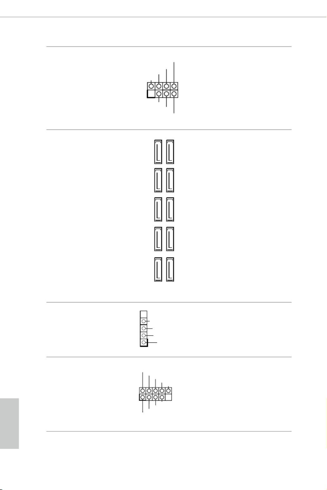
USB 2.0 Headers
(9-pin USB_1_2)
(see p.7, No. 19)
(9-pin USB_3_4)
(see p.7, No. 20)
ere are two headers
on this motherboard.
Each USB 2.0 header can
support two ports.
1
+5V
DUMMY
PLED+
PLED+
PLED-
DUMMY
SPEAKER
DUMMY
GND
GND
P+
P-
U RSB_PW
P+
P-
U RSB_PW
1
SATA3_3
SATA3_4
SATA3_5
SATA3_6
SATA3_7
SATA3_8
SATA3_A1
SATA3_A2
SATA3_1
SATA3_2
1
U RSB_PW
P-
P+
GND

English
29
X370 Taichi
1
IntA_PB_D+
Dummy
IntA_PB_D-
GND
IntA_PB_SSTX+
GND
IntA_PB_SSTX-
IntA_PB_SSRX+
IntA_PB_SSRX-
VbusVbus
Vbus
IntA_PA_SSRX-
IntA_PA_SSRX+
GND
IntA_PA_SSTX-
IntA_PA_SSTX+
GND
IntA_PA_D-
IntA_PA_D+
USB 3.0 Header
(19-pin USB3_7_8)
(see p.7, No. 8)
(19-pin USB3_9_10)
(see p.7, No. 7)
Besides four USB 3.0 ports
on the I/O panel, there
are two headers on this
motherboard. Each USB
3.0 header can support
two ports.
Front Panel Audio Header
(9-pin HD_AUDIO1)
(see p.7, No. 25)
is header is for
connecting audio devices
to the front audio panel.
Chassis Fan Connectors
(4-pin CHA_FAN1)
(see p.7, No. 11)
(4-pin CHA_FAN2)
(see p.7, No. 22)
Please connect fan cables
to the fan connectors and
match the black wire to
the ground pin.
J_SENSE
OUT2_L
1
MIC_RET
PRESENCE#
GND
OUT2_R
MIC2_R
MIC2_L
OUT_RET
1. High Denition Audio supports Jack Sensing, but the panel wire on the chassis must sup-
port HDA to function correctly. Please follow the instructions in our manual and chassis
manual to install your system.
2. If you use an AC’97 audio panel, please install it to the front panel audio header by the
steps below:
A. Connect Mic_ IN (MIC) to MIC2_L.
B. Connect Audio_R (RIN) to OUT2_R and Audio_L (LIN) to OUT2_L.
C. Connect Ground (GND) to Ground (GND).
D. MIC_RET and OUT_RET are for the HD audio panel only. You don’t need to connect
them for the AC’97 audio panel.
E. To activate the front mic, go to the “FrontMic” Tab in the Realtek Control panel and
adjust “Recording Volume”.
GND
FAN_V OLTAG E
CHA_FAN_SPEED
FAN_SPEED_CONTROL 4
3
2
1
GN D
FAN_SPE ED
FAN_SPE ED_CONTRO L
FAN_VOLTAGE
1 2 3 4

English
32
2.7 Smart Switch
e motherboard has Clear CMOS Switch, allowing users to quickly clear the
CMOS values.
Clear CMOS Switch
(CLRCBTN)
(see p.9, No. 15)
Clear CMOS Switch
allows users to quickly
clear the CMOS values.
is function is workable only when you power o your computer and unplug the power
supply.

English
36
Step 3
Align and insert the ASRock SLI_HB_
Bridge_2S Card to the goldngers on each
graphics card. Make sure the ASRock SLI_
HB_Bridge_2S Card is rmly in place.
Step 4
Connect a VGA cable or a DVI cable to the
monitor connector or the DVI connector of
the graphics card that is inserted to PCIE2
slot.
ASRock SLI_HB_Bridge_2S Card
SLI_HB_Bridge_2S Card

English
37
X370 Taichi
2.9.2 Driver Installation and Setup
Install the graphics card drivers to your system. Aer that, you can enable the
Multi-Graphics Processing Unit (GPU) in the NVIDIA® nView system tray utility.
Please follow the below procedures to enable the multi-GPU.
For SLITM and Quad SLITM mode
Step 1
Double-click the NVIDIA Control Panel
icon in the Windows® system tray.
Step 2
In the le pane, click Set SLI and PhysX
conguration Maximize 3D . en select
performance Apply and click .
Step 3
Reboot your system.
Step 4
You can freely enjoy the benets of SLITM
or Quad SLITM.

English
38
2.10 CrossFireXTM and Quad CrossFireXTM Operation Guide
is motherboard supports CrossFireXTM and Quad CrossFireXTM that allows you
to install up to two identical PCI Express p44-x16 graphics cards.
2.10.1 Installing Two CrossFireXTM-Ready Graphics Cards
Step 1
Insert one graphics card into PCIE2 slot
and the other graphics card to PCIE3 slot.
Make sure that the cards are properly
seated on the slots.
Step 2
Connect two graphics cards by installing
a CrossFire Bridge on the CrossFire Bridge
Interconnects on the top of the graphics
cards. (e CrossFire Bridge is provided
with the graphics card you purchase, not
bundled with this motherboard. Please
refer to your graphics card vendor for
details.)
1. You should only use identical CrossFireX
TM-ready graphics cards that are AMD certied.
2. Make sure that your graphics card driver supports AMD CrossFireXTM technology.
Download the drivers from the AMD’s website: www.amd.com
3. Make sure that your power supply unit (PSU) can provide at least the minimum power
your system requires. It is recommended to use a AMD certied PSU. Please refer to the
AMD’s website for details.
4. If you pair a 12-pipe CrossFireXTM
Edition card with a 16-pipe card, both cards will oper-
ate as 12-pipe cards while in CrossFireXTM
mode.
5. Dierent CrossFireXTM cards may require dierent methods to enable CrossFireX
TM.
Please refer to AMD graphics card manuals for detailed installation guide.
CrossFire Bridge

English
39
X370 Taichi
Step 3
Connect a VGA cable or a DVI cable to the
monitor connector or the DVI connec-
tor of the graphics card that is inserted to
PCIE2 slot.

English
40
Step 1
Power on your computer and boot into OS.
Step 2
Remove the AMD drivers if you have any VGA drivers installed in your system.
Step 3
Install the required drivers and CATALYST Control Center then restart your
computer. Please check AMD’s website for details.
2.10.2 Driver Installation and Setup
Step 4
Double-click the AMD Catalyst Control
Center icon in the Windows® system tray.
Step 5
In the le pane, click and Performance
then AMD CrossFireXTM . en select
Enable AMD CrossFireX and click Apply.
Select the GPU number according to your
graphics card and click .Apply
AMD Catalyst Control Center
e Catalyst Uninstaller is an optional download. We recommend using this utility to un-
install any previously installed Catalyst drivers prior to installation. Please check AMD’s
website for AMD driver updates.

English
42
ABC
Step 3
Move the stando based on the
module type and length.
e stando is placed at the nut
location C by default. Skip Step 3
and 4 and go straight to Step 5 if you
are going to use the default nut.
Otherwise, release the stando by
hand.
ABC
Step 4
Peel o the yellow protective lm on
the nut to be used. Hand tighten the
stando into the desired nut location
on the motherboard.
Step 5
Align and gently insert the M.2
(NGFF) SSD module into the M.2
slot. Please be aware that the M.2
(NGFF) SSD module only ts in one
orientation.
ABC
ABC 20o

English
46
BCD A
Step 3
Move the stando based on the
module type and length.
e stando is placed at the nut
location D by default. Skip Step 3 and
4 and go straight to Step 5 if you are
going to use the default nut.
Otherwise, release the stando by
hand.
BCD A
Step 4
Peel o the yellow protective lm on
the nut to be used. Hand tighten the
stando into the desired nut location
on the motherboard.
ABCD
ABCD 20
o
Step 5
Align and gently insert the M.2
(NGFF) SSD module into the M.2
slot. Please be aware that the M.2
(NGFF) SSD module only ts in one
orientation.
D
Step 6
Tighten the screw with a screwdriver
to secure the module into place.
Please do not overtighten the screw as
this might damage the module.

English
57
X370 Taichi
3.3.4 Setting
In the "Setting" page, you can change the language, select the server location, and
determine if you want to automatically run the ASRock Live Update & APP Shop
on Windows startup.

English
60
Chapter 4 UEFI SETUP UTILITY
4.1 Introduction
is section explains how to use the UEFI to congure your SETUP UTILITY
system. You may run the UEFI S by pressing <F2> or <Del> right ETUP UTILITY
aer you power on the computer, otherwise, the Power-On-Self-Test (POST) will
continue with its test routines. If you wish to enter the UEFI SETUP UTILITY aer
POST, restart the system by pressing <Ctl> + <Alt> + <Delete>, or by pressing the
reset button on the system chassis. You may also restart by turning the system o
and then back on.
4.1.1 UEFI Menu Bar
e top of the screen has a menu bar with the following selections:
Main For setting system time/date information
OC Tweaker For overclocking congurations
Advanced For advanced system congurations
Tool Useful tools
H/W Monitor Displays current hardware status
Security For security settings
Boot For conguring boot settings and boot priority
Exit Exit the current screen or the UEFI Setup Utility
Because the UEFI soware is constantly being updated, the following UEFI setup
screens and descriptions are for reference purpose only, and they may not exactly
match what you see on your screen.

English
62
4.2 Main Screen
When you enter the UEFI SETUP UTILITY, the Main screen will appear and
display the system overview.

English
63
X370 Taichi
4.3 OC Tweaker Screen
In the OC Tweaker screen, you can set up overclocking features.
Voltage Conguration
CPU Vcore Voltage
Congure the voltage for the CPU Vcore.
CPU Load-Line Calibration
CPU Load-Line Calibration helps prevent CPU voltage droop when the system is
under heavy loading.
GT Voltage
Congure the voltage for the integrated GPU.
GT Load-Line Calibration
GT Load-Line Calibration helps prevent integrated GPU voltage droop when the
system is under heavy load.
Because the UEFI soware is constantly being updated, the following UEFI setup
screens and descriptions are for reference purpose only, and they may not exactly
match what you see on your screen.

English
64
CPU OVP
Congure the CPU OVP (Over Voltage Protection).
CPU OCP
Congure the CPU OCP (Over Current Protection).
UVP
Congure the UVP (Under Voltage Protection).
DRAM Voltage
Use this to select DRAM Voltage. e default value is [Auto].
VPPM
Congure the VPPM.
2.50V_PROM Voltage
Use this to select 2.50V_PROM Voltage. e default value is [Auto].
VTT_DDR
Congure the VTT DDR voltage. e default value is [Auto].
+1.8 Voltage
Use this to select +1.8 Voltage. e default value is [Auto].
VDDP
Congure the VDDP.
1.05V_PROM Voltage
Congure the voltage for the 1.05V PROM.

English
65
X370 Taichi
4.4 Advanced Screen
In this section, you may set the congurations for the following items: CPU
Conguration, North Bridge Conguration, South Bridge Conguration, Storage-
Conguration, Super IO Conguration and ACPI Conguration.
UEFI Conguration
Active Page on Entry
Select the default page when entering the UEFI setup utility.
Full HD UEFI
When [Auto] is selected, the resolution will be set to 1920 x 1080 if the monitor
supports Full HD resolution. If the monitor does not support Full HD resolution,
then the resolution will be set to 1024 x 768. When [Disable] is selected, the
resolution will be set to 1024 x 768 directly.
Setting wrong values in this section may cause the system to malfunction.

English
69
X370 Taichi
4.4.4 Storage Conguration
SATA Controller(s)
Enable/disable the SATA controllers.
SATA Mode
AHCI: Supports new features that improve performance.
RAID: Combine multiple disk drives into a logical unit.
English
70
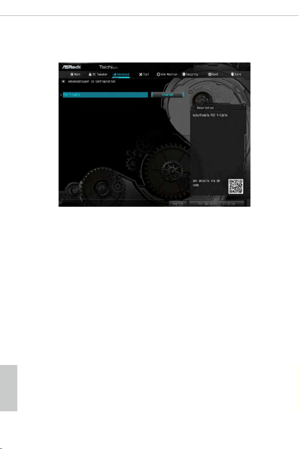
4.4.5 Super IO Conguration
PS2 Y-Cable
Enable the PS2 Y-Cable or set this option to Auto.
Specyfikacje produktu
| Marka: | Asrock |
| Kategoria: | płyta główna |
| Model: | X370 Taichi |
| Rodzaj zasilania: | ATX |
| Szerokość produktu: | 305 mm |
| Głębokość produktu: | 244 mm |
| Bluetooth: | Tak |
| Wersja Bluetooth: | 4.2 |
| Certyfikaty: | FCC, CE, WHQL, ErP/EuP |
| Wyjścia słuchawkowe: | 1 |
| Obsługiwane systemy operacyjne Windows: | Windows 10 Education x64, Windows 10 Enterprise x64, Windows 10 Home x64, Windows 10 Pro x64 |
| Przeznaczenie: | PC |
| Ilość portów Ethernet LAN (RJ-45): | 1 |
| Wi-Fi: | Tak |
| Standardy Wi- Fi: | 802.11a, Wi-Fi 5 (802.11ac), 802.11b, 802.11g, Wi-Fi 4 (802.11n) |
| Przewody: | SATA |
| Kod zharmonizowanego systemu (HS): | 84733020 |
| Kanały wyjścia audio: | 7.1 kan. |
| Przewodowa sieć LAN: | Tak |
| Instrukcja szybkiej instalacji: | Tak |
| Producent procesora: | AMD |
| Ilość portów USB 3.2 Gen 1 (3.1 Gen 1) Typu-A: | 6 |
| Obsługiwane rodzaje pamięci: | DDR4-SDRAM |
| Typ slotów pamięci: | DIMM |
| Liczba gniazd pamięci: | 4 |
| Bez kody korekcyjnego: | Tak |
| Obsługiwane prędkości zegara pamięci: | 2133,2400,2933,3200 MHz |
| Maksymalna pojemność pamięci: | 64 GB |
| Obsługa kanałów pamięci: | Dwukanałowy |
| Gniazdo procesora: | Socket AM4 |
| Procesor: | AMD A |
| Rodzina płyt z chipsetami: | AMD |
| Rodzaj płyty: | ATX |
| Układ płyty głównej: | AMD X370 |
| Typ BIOS: | UEFI |
| Liczba gniazd M.2 (M): | 1 |
| Gniazdo zasilania ATX (24-pin): | Tak |
| Złącze zasilacza EPS (8-pin): | Tak |
| Ilość złączy SATA III: | 10 |
| Ilość gniazd USB 2.0: | 2 |
| Łącza USB 3.2 Gen 1 (3.1 Gen 1): | 2 |
| Gniazdo wentylatora procesora: | Tak |
| Ilość gniazd w podstawie wentylatora: | 3 |
| Złącze audio na przednim panelu: | Tak |
| Liczba portów PS/2: | 1 |
| Ilość portów USB 3.2 Gen 2 (3.1 Gen 2) Typu-A: | 1 |
| Ilość portów USB 3.2 Gen 2 (3.1 Gen 2) Typu-C: | 1 |
| Mikrofon: | Tak |
| Zawiera sterowniki: | Tak |
| Maksymalna liczba procesorów SMP: | 1 |
| Pamięć niebuforowana: | Tak |
| Gniazda PCI Express x16 (Gen 3.x): | 3 |
| Obsługa przetwarzania równoległego: | 2-Way CrossFireX, Quad-GPU SLI |
| Rodzaj interfejsu sieci Ethernet: | Gigabit Ethernet |
| Kontroler LAN: | Intel® I211-AT |
| Funkcja Wake-On-LAN: | Tak |
| Korekcja ECC: | Tak |
| Monitorowanie stanu komputera: | CPU, FAN, Temperature, Voltage |
| Złącze zasilania 12V: | Tak |
| Wersja ACPI: | 5.1 |
| Wejście cyfrowe audio: | 1 |
| Gniazda PCI Express x1 (Gen 2.x): | 2 |
| Przycisk clear CMOS: | Tak |
| Port S/PDIF: | Tak |
| Złącze audio: | Tak |
Potrzebujesz pomocy?
Jeśli potrzebujesz pomocy z Asrock X370 Taichi, zadaj pytanie poniżej, a inni użytkownicy Ci odpowiedzą
Instrukcje płyta główna Asrock

25 Marca 2025
1 Stycznia 2025
27 Grudnia 2024
15 Października 2024
15 Października 2024
15 Października 2024
14 Października 2024
10 Października 2024
5 Października 2024
3 Października 2024
Instrukcje płyta główna
- płyta główna Supermicro
- płyta główna Gigabyte
- płyta główna Asus
- płyta główna MSI
- płyta główna NZXT
- płyta główna Biostar
- płyta główna Sharkoon
- płyta główna ECS
- płyta główna Evga
- płyta główna Intel
- płyta główna Foxconn
- płyta główna Advantech
- płyta główna Elitegroup
- płyta główna EPoX
Najnowsze instrukcje dla płyta główna

27 Marca 2025
27 Marca 2025

10 Marca 2025

4 Marca 2025
12 Lutego 2025
12 Lutego 2025
12 Lutego 2025
12 Lutego 2025
12 Lutego 2025
12 Lutego 2025