Instrukcja obsługi Asrock B450M/ac
Asrock
płyta główna
B450M/ac
Przeczytaj poniżej 📖 instrukcję obsługi w języku polskim dla Asrock B450M/ac (87 stron) w kategorii płyta główna. Ta instrukcja była pomocna dla 16 osób i została oceniona przez 2 użytkowników na średnio 4.5 gwiazdek
Strona 1/87


Version 1.0
Published May 2019
Copyright©2019 ASRock INC. All rights reserved.
Copyright Notice:
No part of this documentation may be reproduced, transcribed, transmitted, or
translated in any language, in any form or by any means, except duplication of
documentation by the purchaser for backup purpose, without written consent of
ASRock Inc.
Products and corporate names appearing in this documentation may or may not
be registered trademarks or copyrights of their respective companies, and are used
only for identication or explanation and to the owners’ benet, without intent to
infringe.
Disclaimer:
Specications and information contained in this documentation are furnished for
informational use only and subject to change without notice, and should not be
constructed as a commitment by ASRock. ASRock assumes no responsibility for
any errors or omissions that may appear in this documentation.
With respect to the contents of this documentation, ASRock does not provide
warranty of any kind, either expressed or implied, including but not limited to
the implied warranties or conditions of merchantability or tness for a particular
purpose.
In no event shall ASRock, its directors, ocers, employees, or agents be liable for
any indirect, special, incidental, or consequential damages (including damages for
loss of prots, loss of business, loss of data, interruption of business and the like),
even if ASRock has been advised of the possibility of such damages arising from any
defect or error in the documentation or product.
is device complies with Part 15 of the FCC Rules. Operation is subject to the following
two conditions:
(1) this device may not cause harmful interference, and
(2) this device must accept any interference received, including interference that
may cause undesired operation.
CALIFORNIA, USA ONLY
e Lithium battery adopted on this motherboard contains Perchlorate, a toxic substance
controlled in Perchlorate Best Management Practices (BMP) regulations passed by the
California Legislature. When you discard the Lithium battery in California, USA, please
follow the related regulations in advance.
“Perchlorate Material-special handling may apply, see www.dtsc.ca.gov/hazardouswaste/
perchlorate”
ASRock Website: http://www.asrock.com

AUSTRALIA ONLY
Our goods come with guarantees that cannot be excluded under the Australian
Consumer Law. You are entitled to a replacement or refund for a major failure and
compensation for any other reasonably foreseeable loss or damage caused by our
goods. You are also entitled to have the goods repaired or replaced if the goods fail
to be of acceptable quality and the failure does not amount to a major failure. If
you require assistance please call ASRock Tel : +886-2-28965588 ext.123 (Standard
International call charges apply)
e terms HDMI® and HDMI High-Denition Multimedia Interface, and the
HDMI logo are trademarks or registered trademarks of HDMI Licensing LLC in the
United States and other countries.

CE Warning
is device complies with directive 2014/53/EU issued by the Commision of the European
Community.
is equipment complies with EU radiation exposure limits set forth for an uncontrolled
environment.
is equipment should be installed and operated with minimum distance 20cm between
the radiator & your body.
Operations in the 5.15-5.35GHz band are restricted to indoor usage only.
Radio transmit power per transceiver type
Function Frequency Maximum Output Power (EIRP)
WiFi
2400-2483.5 MHz 18.5 + / -1.5 dbm
5150-5250 MHz 21.5 + / -1.5 dbm
5250-5350 MHz 18.5 + / -1.5 dbm (no TPC)
21.5 + / -1.5 dbm (TPC)
5470-5725 MHz 25.5 + / -1.5 dbm (no TPC)
28.5 + / -1.5 dbm (TPC)
Bluetooth 2400-2483.5 MHz 8.5 + / -1.5 dbm

Contents
Chapter 1 Introduction 1
1.1 Package Contents 1
1.2 Specications 2
1.3 Motherboard Layout 7
1.4 I/O Panel 9
1.5 WiFi-802.11ac Module and ASRock WiFi 2.4/5 GHz
Antenna 11
Chapter 2 Installation 13
2.1 Installing the CPU 14
2.2 Installing the CPU Fan and Heatsink 16
2.3 Installing Memory Modules (DIMM) 25
2.4 Expansion Slots (PCI Express Slots) 28
2.5 Jumpers Setup 29
2.6 Onboard Headers and Connectors 30
2.7 M.2_SSD (NGFF) Module Installation Guide (M2_1) 35
Chapter 3 Software and Utilities Operation 38
3.1 Installing Drivers 38
3.2 A-Tuning 39
3.2.1 Installing A-Tuning 39
3.2.2 Using A-Tuning 39
3.3 ASRock Live Update & APP Shop 42
3.3.1 UI Overview 42

3.3.2 Apps 43
3.3.3 BIOS & Drivers 46
3.3.4 Setting 47
3.5 ASRock Polychrome SYNC 48
Chapter 4 UEFI SETUP UTILITY 51
4.1 Introduction 51
4.1.1 UEFI Menu Bar 51
4.1.2 Navigation Keys 52
4.2 Main Screen 53
4.3 OC Tweaker Screen 54
4.4 Advanced Screen 57
4.4.1 CPU Conguration 58
4.4.2 North Bridge Conguration 59
4.4.3 South Bridge Conguration 60
4.4.4 Storage Conguration 61
4.4.5 ACPI Conguration 62
4.4.6 Trusted Computing 63
4.4.7 AMD CBS 64
4.4.8 AMD PBS 72
4.5 Tools 73
4.6 Hardware Health Event Monitoring Screen 74
4.7 Security Screen 76
4.8 Boot Screen 77
4.9 Exit Screen 79

B450M/ac
1
English
Chapter 1 Introduction
ank you for purchasing ASRock B450M/ac motherboard, a reliable motherboard
produced under ASRock’s consistently stringent quality control. It delivers excellent
performance with robust design conforming to ASRock’s commitment to quality
and endurance.
In this manual, Chapter 1 and 2 contains the introduction of the motherboard
and step-by-step installation guides. Chapter 3 contains the operation guide of the
soware and utilities. Chapter 4 contains the conguration guide of the BIOS setup.
1.1 Package Contents
• ASRock B450M/ac Motherboard (Micro ATX Form Factor)
• ASRock B450M/ac Quick Installation Guide
• ASRock B450M/ac Support CD
• 1 x I/O Panel Shield
• 2 x Serial ATA (SATA) Data Cables (Optional)
• 2 x ASRock WiFi 2.4/5 GHz Antennas (Optional)
• 1 x Screw for M.2 Socket (Optional)
Because the motherboard specications and the BIOS soware might be updated, the
content of this manual will be subject to change without notice. In case any modica-
tions of this manual occur, the updated version will be available on ASRock’s website
without further notice. If you require technical support related to this motherboard,
please visit our website for specic information about the model you are using. You
may nd the latest VGA cards and CPU support list on ASRock’s website as well.
ASRock website http://www.asrock.com.

English
2
1.2 Specications
Platform • Micro ATX Form Factor
• 2oz Copper PCB
• Solid Capacitor design
CPU • AMD AM4 Socket
• Digi Power design
• 9 Power Phase design
Chipset • AMD Promontory B450
Memory • Dual Channel DDR4 Memory Technology
• 4 x DDR4 DIMM Slots
• AMD Ryzen series CPUs (Pinnacle Ridge) support DDR4
3200+(OC)/2933(OC)/2667/2400/2133 ECC & non-ECC, un-
buered memory*
• AMD Ryzen series CPUs (Summit Ridge) support DDR4
3200+(OC)/2933(OC)/2667/2400/2133 ECC & non-ECC, un-
buered memory*
• AMD Ryzen series CPUs (Raven Ridge) support DDR4
3200+(OC)/2933/2667/2400/2133 non-ECC, un-buered
memory*
* For Ryzen Series CPUs (Raven Ridge), ECC is only supported
with PRO CPUs.
* Please refer to Memory Support List on ASRock’s website for
more information. (http://www.asrock.com/)
* Please refer to page 24 for DDR4 UDIMM maximum frequency
support.
• Max. capacity of system memory: 64GB
• 15μ Gold Contact in DIMM Slots
Expansion
Slot
AMD Ryzen series CPUs (Summit Ridge and Pinnacle Ridge)
• 1 x PCI Express 3.0 x16 Slot (PCIE1: x16 mode)*
• 1 x PCI Express 2.0 x16 Slot (PCIE2: p8-x4 mode)
AMD Ryzen series CPUs (Raven Ridge)
• 1 x PCI Express 3.0 x16 Slot (PCIE1: x8 mode)*
• 1 x PCI Express 2.0 x16 Slot (PCIE2: p8-x4 mode)

B450M/ac
3
English
AMD Athlon series CPUs
• 1 x PCI Express 3.0 x16 Slot (PCIE1: p9-x4 mode)*
• 1 x PCI Express 2.0 x16 Slot (PCIE2: p9-x4 mode)
* Supports NVMe SSD as boot disks
• Supports AMD Quad CrossFireXTM and CrossFireXTM
• 1 x Vertical M.2 Socket (Key E) with the bundled WiFi-
802.11ac module (on the rear I/O)
Graphics • Integrated AMD RadeonTM Vega Series Graphics in Ryzen
Series APU*
* Actual support may vary by CPU
• DirectX 12, Pixel Shader 5.0
• Shared memory default 2GB. Max Shared memory supports
up to 16GB.
* e Max shared memory 16GB requires 32GB system memory
installed.
• Supports HDMI with max. resolution up to 4K x 2K
(4096x2160) @ 24Hz / (3840x2160) @ 30Hz
• Supports Auto Lip Sync, Deep Color (12bpc), xvYCC and
HBR (High Bit Rate Audio) with HDMI 1.4 Port (Compliant
HDMI monitor is required)
• Supports HDCP 1.4 with HDMI 1.4 Port
• Supports 4K Ultra HD (UHD) playback with HDMI 1.4 Port
Audio • 7.1 CH HD Audio with Content Protection (Realtek ALC892
Audio Codec)
• Premium Blu-ray Audio support
• Supports Surge Protection
• ELNA Audio Caps
LAN • PCIE p9-x1 Gigabit LAN 10/100/1000 Mb/s
• Realtek RTL8111H
• Supports Wake-On-LAN
• Supports Lightning/ESD Protection
• Supports Energy Ecient Ethernet 802.3az
• Supports PXE

English
4
Wireless
LAN
• Intel® 802.11ac WiFi Module
• Supports IEEE 802.11a/b/g/n/ac
• Supports Dual-Band (2.4/5 GHz)
• Supports high speed wireless connections up to 433Mbps
• Supports Bluetooth 4.2 / 3.0 + High speed class II
Rear Panel
I/O
• 2 x Antenna Ports
• 1 x HDMI Port
• 2 x USB 2.0 Ports (Supports ESD Protection)
• 4 x USB 3.2 Gen1 Ports (Supports ESD Protection)
• 1 x RJ-45 LAN Port with LED (ACT/LINK LED and SPEED
LED)
• HD Audio Jacks: Line in / Front Speaker / Microphone
Storage • 4 x SATA3 6.0 Gb/s Connectors, support RAID (RAID 0,
RAID 1 and RAID 10), NCQ, AHCI and Hot Plug
• 1 x Ultra M.2 Socket (M2_1), supports M Key type
2242/2260/2280 M.2 PCI Express module up to Gen3 p10-x4 (32
Gb/s) (with Summit Ridge, Raven Ridge and Pinnacle Ridge)
or Gen3 x2 (16 Gb/s) (with Athlon 2xxGE series APU)*
* Supports NVMe SSD as boot disks
* Supports ASRock U.2 Kit
Connector • 1 x Chassis Intrusion Header
• 1 x Power LED and Speaker Header
• 1 x RGB LED Header
* Supports in total up to 12V/3A, 36W LED Strip
• 1 x Addressable LED Header
* Supports in total up to 5V/3A, 15W LED Strip
• 1 x AMD Fan LED Header
*e AMD Fan LED Header supports LED strips of maximum
load of 3A (36W) and length up to 2.5M.
• 1 x CPU Fan Connector (4-pin)
* e CPU Fan Connector supports the CPU fan of maximum
1A (12W) fan power.

B450M/ac
5
English
• 1 x Chassis Fan Connector (3-pin)
* e Chassis Fan Connector supports the chassis fan of
maximum 1A (12W) fan power.
• 1 x Chassis/Water Pump Fan Connector (4-pin) (Smart Fan
Speed Control)
* e Chassis/Water Pump Fan supports the water cooler fan of
maximum 2A (24W) fan power.
* CHA_FAN1 can auto detect if 3-pin or 4-pin fan is in use.
• 1 x 24 pin ATX Power Connector
• 1 x 8 pin 12V Power Connector
• 1 x Front Panel Audio Connector
• 1 x AMD LED Fan USB Header
• 2 x USB 2.0 Headers (Support 4 USB 2.0 ports) (Supports ESD
Protection)
• 1 x USB 3.2 Gen1 Header (Supports 2 USB 3.2 Gen1 ports)
(Supports ESD Protection)
BIOS
Feature
• AMI UEFI Legal BIOS with multilingual GUI support
• Supports “Plug and Play”
• ACPI 5.1 compliance wake up events
• Supports jumperfree
• SMBIOS 2.3 support
• DRAM Voltage multi-adjustment
Hardware
Monitor
• Temperature Sensing: CPU, Chassis, Chassis/Water Pump
Fans
• Fan Tachometer: CPU, Chassis, Chassis/Water Pump Fans
• Quiet Fan (Auto adjust chassis fan speed by CPU tempera-
ture): CPU, Chassis, Chassis/Water Pump Fans
• Fan Multi-Speed Control: CPU, Chassis, Chassis/Water
Pump Fans
• CASE OPEN detection
• Voltage monitoring: +12V, +5V, +3.3V, Vcore
OS • Microso® Windows® 10 64-bit
Certica-
tions
• FCC, CE
• ErP/EuP ready (ErP/EuP ready power supply is required)

English
6
Please realize that there is a certain risk involved with overclocking, including adjust-
ing the setting in the BIOS, applying Untied Overclocking Technology, or using third-
party overclocking tools. Overclocking may aect your system’s stability, or even cause
damage to the components and devices of your system. It should be done at your own
risk and expense. We are not responsible for possible damage caused by overclocking.
* For detailed product information, please visit our website:
http://www.asrock.com

B450M/ac
7
English
1.3 Motherboard Layout
3 42
6
5
7
8
9
10
1
1417
16
12
11
1819 13
BIOS
ROM
ATXPWR1
Supe r
I/O
CLR CMO S1
1
PCIE1
1
USB_ 3_4
HD_AUDIO1
1
CPU_ FAN1
Top:
LIN E IN
Cen t er:
FRO NT
Bot t om:
MIC I N
RJ- 45 LA N
US 2.B 0
T: 1USB
B: USB 2
SOCKET AM4
CMOS
Batt ery
ATX 112 V
M2_1
Ultr M.a 2
PCIe x 4 Ge n3
USB 3_5_6
1
CHA_FAN1
CHA_FAN2
HDL ED ESET R
PL ED PW RBT N
PAN EL 1
1
RoHS
SPK_ PLE D 1
1
DDR 4_A1 (64 bit, 288-pin m odul e)
DDR 4_A2 (64 bit, 288-pin m odul e)
DDR 4_B1 (6 4 bit, 288- pi n m odule)
DDR 4_B2 (6 4 bit, 288- pi n m odule)
PCIE2
AMD
Promont ory
B450
US 3. Gen1B 2
T: 1USB
B: USB 2
US 3. Gen1B 2
T: 3USB
B: USB 4
1
AM D _F AN _ LED 1
1
USB_ 7
1
M 3M 2M 1 2_1_CT2_1_CT2_1_CT
1
USB_ 5_6
SAT A3 _3
SAT A3 _4
SAT A3 _1
SAT A3 _2
22
23
HDM I1
M2_WIFI
20
ADDR _L ED1
1
RG B _HE ADE R 1
B450M/ac
CI1
1521

English
8
No. Description
1 ATX 12V Power Connector (ATX12V1)
2 CPU Fan Connector (CPU_FAN1)
3 2 x 288-pin DDR4 DIMM Slots (DDR4_A1, DDR4_B1)
4 2 x 288-pin DDR4 DIMM Slots (DDR4_A2, DDR4_B2)
5 AMD Fan LED Header (AMD_FAN_LED1)
6 ATX Power Connector (ATXPWR1)
7 USB 3.2 Gen1 Header (USB3_5_6)
8 AMD LED Fan USB Header (USB_7)
9 SATA3 Connector (SATA3_3)
10 SATA3 Connector (SATA3_4)
11 SATA3 Connector (SATA3_2)
12 SATA3 Connector (SATA3_1)
13 System Panel Header (PANEL1)
14 Power LED and Speaker Header (SPK_PLED1)
15 Chassis Intrusion Header (CI1)
16 Chassis Fan Connector (CHA_FAN2)
17 USB 2.0 Header (USB_3_4)
18 USB 2.0 Header (USB_5_6)
19 Clear CMOS Jumper (CLRCMOS1)
20 RGB LED Header (RGB_HEADER1)
21 Addressable LED Header (ADDR_LED1)
22 Front Panel Audio Header (HD_AUDIO1)
23 Chassis/Water Pump Fan Connector (CHA_FAN1)

B450M/ac
9
English
1.4 I/O Panel
No. No.Description Description
1 LAN RJ-45 Port* 6 USB 3.2 Gen1 Ports (USB3_1_2)
2 Line In (Light Blue)** 7 HDMI Port
3 Front Speaker (Lime)** 8 USB 2.0 Ports (USB_1_2)
4 Microphone (Pink)** 9 Antenna Ports
5 USB 3.2 Gen1 Ports (USB3_3_4)
* ere are two LEDs on each LAN port. Please refer to the table below for the LAN port LED indications.
Activity / Link LED Speed LED
Status StatusDescription Description
O ONo Link 10Mbps connection
Blinking Data Activity Orange 100Mbps connection
On Link Green 1Gbps connection
ACT/LINK LED
SPEED LED
LAN Port
6 589 7
1
4
3
2
** Function of the Audio Ports in 7.1-channel Conguration:
Port Function
Light Blue (Rear panel) Rear Speaker Out
Lime (Rear panel) Front Speaker Out
Pink (Rear panel) Central /Subwoofer Speaker Out
Lime (Front panel) Side Speaker Out

English
10
1.5 WiFi-802.11ac Module and ASRock WiFi 2.4/5 GHz
Antenna
WiFi-802.11ac + BT Module
is motherboard comes with an exclusive WiFi 802.11 a/b/g/n/ac + BT v4.2
module (pre-installed on the rear I/O panel) that oers support for WiFi 802.11 a/b/
g/n/ac connectivity standards and Bluetooth v4.2. WiFi + BT module is an easy-to-
use wireless local area network (WLAN) adapter to support WiFi + BT. Bluetooth
v4.2 standard features Smart Ready technology that adds a whole new class of
functionality into the mobile devices. BT 4.2 also includes Low Energy Technology
and ensures extraordinary low power consumption for PCs.
* e transmission speed may vary according to the environment.

B450M/ac
11
English
WiFi Antennas Installation Guide
Step 1
Prepare the WiFi 2.4/5 GHz Antennas that come
with the package.
Step 2
Connect the two WiFi 2.4/5 GHz Antennas to
the antenna connectors. Turn the antenna clock-
wise until it is securely connected.
Step 3
Set the WiFi 2.4/5 GHz Antenna as shown in the
illustration.
*You may need to adjust the direction of
the antenna for a stronger signal.

English
12
is is a Micro ATX form factor motherboard. Before you install the motherboard,
study the conguration of your chassis to ensure that the motherboard ts into it.
Pre-installation Precautions
Take note of the following precautions before you install motherboard components
or change any motherboard settings.
• Make sure to unplug the power cord before installing or removing the motherboard.
Failure to do so may cause physical injuries to you and damages to motherboard
components.
• In order to avoid damage from static electricity to the motherboard’s components,
NEVER place your motherboard directly on a carpet. Also remember to use a grounded
wrist strap or touch a safety grounded object before you handle the components.
• Hold components by the edges and do not touch the ICs.
• Whenever you uninstall any components, place them on a grounded anti-static pad or
in the bag that comes with the components.
• When placing screws to secure the motherboard to the chassis, please do not over-
tighten the screws! Doing so may damage the motherboard.
Chapter 2 Installation

B450M/ac
13
English
2.1 Installing the CPU
Unplug all power cables before installing the CPU.
2
1

English
14
3

B450M/ac
15
English
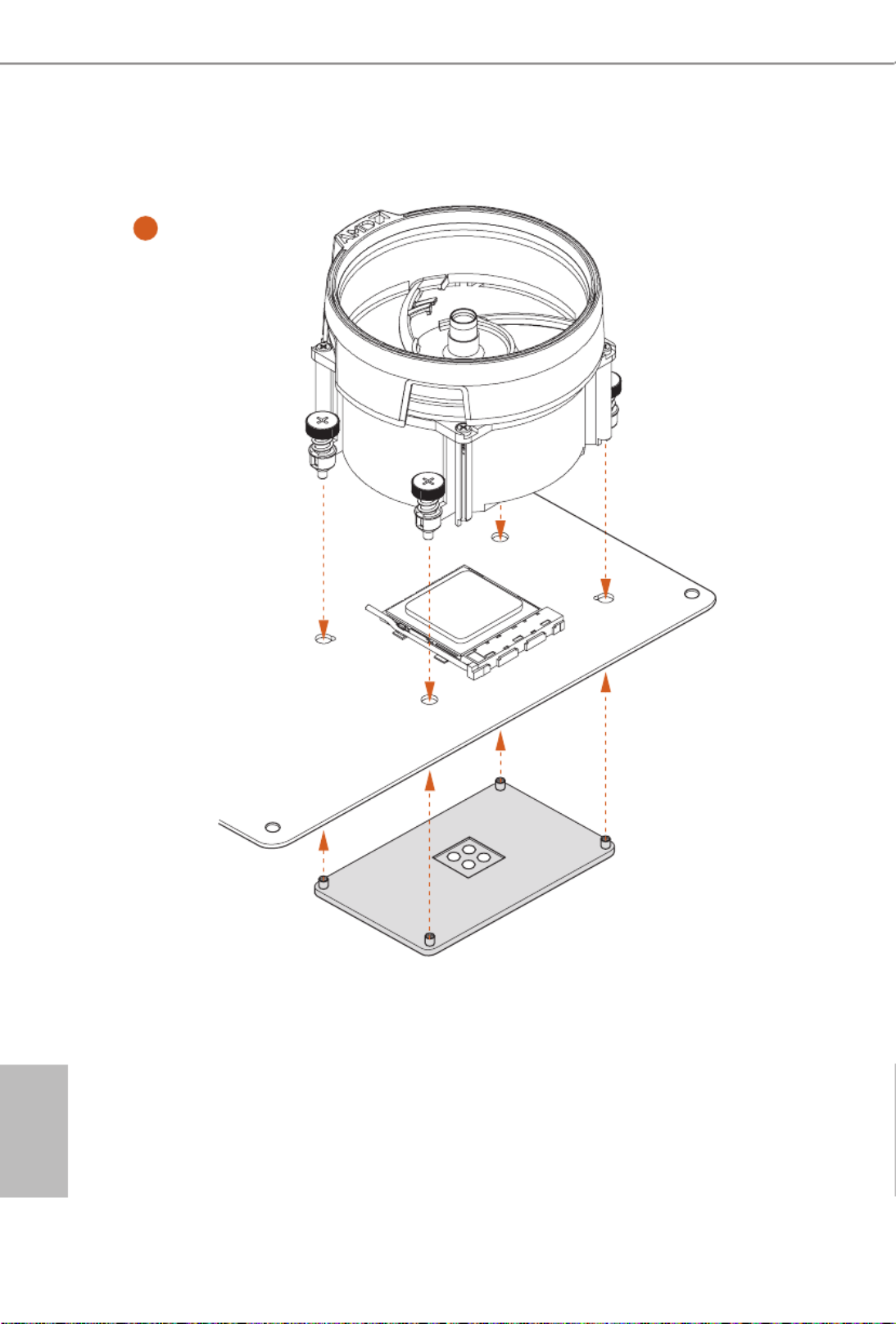
2.2 Installing the CPU Fan and Heatsink
Aer you install the CPU into this motherboard, it is necessary to install a larger
heatsink and cooling fan to dissipate heat. You also need to spray thermal grease
between the CPU and the heatsink to improve heat dissipation. Make sure that the
CPU and the heatsink are securely fastened and in good contact with each other.
Installing the CPU Box Cooler SR1
Please turn o the power or remove the power cord before changing a CPU or heatsink.
1
2

English
16
3
4
C
PU
_
FA N1

B450M/ac
17
English
Installing the AM4 Box Cooler SR2
1
2
English
18
3

B450M/ac
19
English
4-pin FAN cable
RGB LED Cable
+12V
*e diagram shown here are for reference only. Please refer to page 33 for the orientation of
AMD Fan LED Header (AMD_FAN_LED1).
5
CPU_FAN
1
AM
D_
FA N
_
LED
1
4
C
PU
_
FAN1

English
20
Installing the AM4 Box Cooler SR3
1
2

B450M/ac
21
English
3
4

English
22
5
CPU_
FAN1
4-pin FAN cable

B450M/ac
25
English
Ryzen Series CPUs (Summit Ridge):
Ryzen Series CPUs (Raven Ridge):
SR: Single rank DIMM, 1Rx4 or 1Rx8 on DIMM module label
DR: Dual rank DIMM, 2Rx4 or 2Rx8 on DIMM module label
UDIMM Memory Slot Frequency
(Mhz)
A1 A2 B1 B2
- - - 2667SR
- - - 2667DR
- - 2667SR SR
- - 2667DR DR
SR SR SR SR 2667
SR/DR SR/DR 2667DR DR
SR/DR SR/DR SR/DR SR/DR 2133-2400
UDIMM Memory Slot Frequency
(Mhz)
A1 A2 B1 B2
- - -SR 2933
- - - 2667DR
- - 2667SR SR
- - 2667DR DR
SR SR SR SR 2667
SR/DR SR/DR 2667DR DR
SR/DR SR/DR SR/DR SR/DR 2133-2400

English
26
e DIMM only ts in one correct orientation. It will cause permanent damage to
the motherboard and the DIMM if you force the DIMM into the slot at incorrect
orientation.
1
2
3

B450M/ac
27
English
2.4 Expansion Slots (PCI Express Slots)
ere are 2 PCI Express slots on the motherboard.
PCIe slots:
PCIE1 (PCIe 3.0 x16 slot) is used for PCI Express x16 lane width graphics cards.
PCIE2 (PCIe 2.0 x16 slot) is used for PCI Express p33-x4 lane width graphics cards.
PCIe Slot Congurations
Before installing an expansion card, please make sure that the power supply is
switched o or the power cord is unplugged. Please read the documentation of the
expansion card and make necessary hardware settings for the card before you start
the installation.
PCIE1 PCIE2
Ryzen Series CPUs (Pinnacle Ridge) x16 x4
Ryzen Series CPUs (Summit Ridge) x16 x4
Ryzen Series CPUs (Raven Ridge) x8 x4
Athlon 2xxGE series APU x4 x4

English
28
2.5 Jumpers Setup
e illustration shows how jumpers are setup. When the jumper cap is placed on
the pins, the jumper is “Short”. If no jumper cap is placed on the pins, the jumper is
“Open”.
Clear CMOS Jumper
(CLRMOS1)
(see p.7, No. 19)
CLRMOS1 allows you to clear the data in CMOS. To clear and reset the system
parameters to default setup, please turn o the computer and unplug the power
cord from the power supply. Aer waiting for 15 seconds, use a jumper cap to
short the pins on CLRMOS1 for 5 seconds. However, please do not clear the
CMOS right aer you update the BIOS. If you need to clear the CMOS when you
just nish updating the BIOS, you must boot up the system rst, and then shut it
down before you do the clear-CMOS action. Please be noted that the password,
date, time, and user default prole will be cleared only if the CMOS battery is
removed. Please remember toremove the jumper cap aer clearing the CMOS.
If you clear the CMOS, the case open may be detected. Please adjust the BIOS option
“Clear Status” to clear the record of previous chassis intrusion status.
2-pin Jumper

B450M/ac
29
English
2.6 Onboard Headers and Connectors
System Panel Header
(9-pin PANEL1)
(see p.7, No. 13)
Connect the power
button, reset button and
system status indicator on
the chassis to this header
according to the pin
assignments below. Note
the positive and negative
pins before connecting
the cables.
Onboard headers and connectors are NOT jumpers. Do NOT place jumper caps over
these headers and connectors. Placing jumper caps over the headers and connectors
will cause permanent damage to the motherboard.
GND
R #ESE T
PWRBTN#
PLED-
PLED+
GND
HDL ED-
HDL ED+
1
GND
PWRBTN (Power Button):
Connect to the power button on the chassis front panel. You may congure the way to
turn o your system using the power button.
RESET (Reset Button):
Connect to the reset button on the chassis front panel. Press the reset button to
restart the computer if the computer freezes and fails to perform a normal restart.
PLED (System Power LED):
Connect to the power status indicator on the chassis front panel. e LED is on when
the system is operating. e LED keeps blinking when the system is in S1/S3 sleep
state. e LED is o when the system is in S4 sleep state or powered o (S5).
HDLED (Hard Drive Activity LED):
Connect to the hard drive activity LED on the chassis front panel. e LED is on
when the hard drive is reading or writing data.
e front panel design may dier by chassis. A front panel module mainly consists
of power button, reset button, power LED, hard drive activity LED, speaker and etc.
When connecting your chassis front panel module to this header, make sure the wire
assignments and the pin assignments are matched correctly.

English
30
Power LED and Speaker
Header
(7-pin SPK_PLED1)
(see p.7, No. 14)
Please connect the
chassis power LED and
the chassis speaker to this
header.
Serial ATA3 Connectors
(SATA3_1:
see p.7, No. 12)
(SATA3_2:
see p.7, No. 11)
(SATA3_3:
see p.7, No. 9)
(SATA3_4:
see p.7, No. 10)
ese four SATA3
connectors support SATA
data cables for internal
storage devices with up to
6.0 Gb/s data transfer rate.
AMD LED Fan USB
Header
(4-pin USB_7)
(see p.7, No. 8)
is header is used for
connecting the USB
connector on the AMD
SR3 Heatsink.
USB 2.0 Headers
(9-pin USB_3_4)
(see p.7, No. 17)
(9-pin USB_5_6)
(see p.7, No. 18)
ere are two headers
on this motherboard.
Each USB 2.0 header can
support two ports.
SATA3_3
SATA3_4
SATA3_1
SATA3_2
1
USB_PW
R
P-
P+
GND
1
+5V
DUMMY
PLED+
PLED+
PLED-
DUMMY
SPEAKER
DUMMY
GND
GND
P+
P-
U RSB_PW
P+
P-
U RSB_PW
1

B450M/ac
31
English
USB 3.2 Gen1 Header
(19-pin USB3_5_6)
(see p.7, No. 7)
ere is one header on
this motherboard. Each
USB 3.2 Gen1 header can
support two ports.
Front Panel Audio Header
(9-pin HD_AUDIO1)
(see p.7, No. 22)
is header is for
connecting audio devices
to the front audio panel.
Chassis Fan Connector
(3-pin CHA_FAN2)
(see p.7, No. 16)
Please connect fan cable
to the fan connector and
match the black wire to
the ground pin.
GND
FAN_VOLT AG
E
FA
N_SPEED
1. High Denition Audio supports Jack Sensing, but the panel wire on the chassis must
support HDA to function correctly. Please follow the instructions in our manual and
chassis manual to install your system.
2. If you use an AC’97 audio panel, please install it to the front panel audio header by
the steps below:
A. Connect Mic_IN (MIC) to MIC2_L.
B. Connect Audio_R (RIN) to OUT2_R and Audio_L (LIN) to OUT2_L.
C. Connect Ground (GND) to Ground (GND).
D. MIC_RET and OUT_RET are for the HD audio panel only. You don’t need to
connect them for the AC’97 audio panel.
E. To activate the front mic, go to the “FrontMic” Tab in the Realtek Control panel
and adjust “Recording Volume”.
1
IntA_PB_D+
Dummy
IntA_PB_D-
GND
IntA_PB_SSTX+
GND
IntA_PB_SSTX-
IntA_PB_SSRX+
IntA_PB_SSRX-
VbusVbus
Vbus
IntA_PA_SSRX-
IntA_PA_SSRX+
GND
IntA_PA_SSTX-
IntA_PA_SSTX+
GND
IntA_PA_D-
IntA_PA_D+
J_SENSE
OUT2_L
1
MIC_RET
PRESENCE#
GND
OUT2_R
MIC2_R
MIC2_L
OUT_RET

English
32
Chassis/Water Pump Fan
Connectors
(4-pin CHA_FAN2/WP)
(see p.7, No. 23)
is motherboard
provides one 4-Pin water
cooling
chassis
fan
connectors. If you plan to
connect a 3-Pin
chassis
water cooler fan, please
connect it to Pin 1-3.
CPU Fan Connector
(4-pin CPU_FAN1)
(see p.7, No. 2)
is motherboard
provides a 4-Pin CPU fan
(Quiet Fan) connector.
If you plan to connect a
3-Pin CPU fan, please
connect it to Pin 1-3.
ATX Power Connector
(24-pin ATXPWR1)
(see p.7, No. 6)
is motherboard pro-
vides a 24-pin ATX power
connector. To use a 20-pin
ATX power supply, please
plug it along Pin 1 and Pin
13.
ATX 12V Power
Connector
(8-pin ATX12V1)
(see p.7, No. 1)
is motherboard
provides a 8-pin ATX 12V
power connector. To use a
4-pin ATX power supply,
please plug it along Pin 1
and Pin 5.
Chassis Intrusion Header
(2-pin CI1)
(see p.7, No. 15)
is motherboard
supports CASE OPEN
detection feature that
detects if the chassis cove
has been removed. is
feature requires a chassis
with chassis intrusion
detection design.
GND
FAN_VOLTAGE
CHA_FAN_SPEED
F LAN_SPEED_CONTRO 4
3
2
1
FAN_VOLTAGE
GND
CPU_ N_SPEEFA D
FA LN_SPEED_CONTRO
1 2 3 4
12
1
24
13
4 1
8 5
1
Signal
GND
Specyfikacje produktu
| Marka: | Asrock |
| Kategoria: | płyta główna |
| Model: | B450M/ac |
Potrzebujesz pomocy?
Jeśli potrzebujesz pomocy z Asrock B450M/ac, zadaj pytanie poniżej, a inni użytkownicy Ci odpowiedzą
Instrukcje płyta główna Asrock

25 Marca 2025
1 Stycznia 2025
27 Grudnia 2024
15 Października 2024
15 Października 2024
15 Października 2024
14 Października 2024
10 Października 2024
5 Października 2024
3 Października 2024
Instrukcje płyta główna
- płyta główna Supermicro
- płyta główna Gigabyte
- płyta główna Asus
- płyta główna MSI
- płyta główna NZXT
- płyta główna Biostar
- płyta główna Sharkoon
- płyta główna ECS
- płyta główna Evga
- płyta główna Intel
- płyta główna Foxconn
- płyta główna Advantech
- płyta główna Elitegroup
- płyta główna EPoX
Najnowsze instrukcje dla płyta główna

27 Marca 2025
27 Marca 2025

10 Marca 2025

4 Marca 2025
12 Lutego 2025
12 Lutego 2025
12 Lutego 2025
12 Lutego 2025
12 Lutego 2025
12 Lutego 2025